Section 6
Hardee by EVH
Troubleshooting
LR50160 Long Reach Mower 24
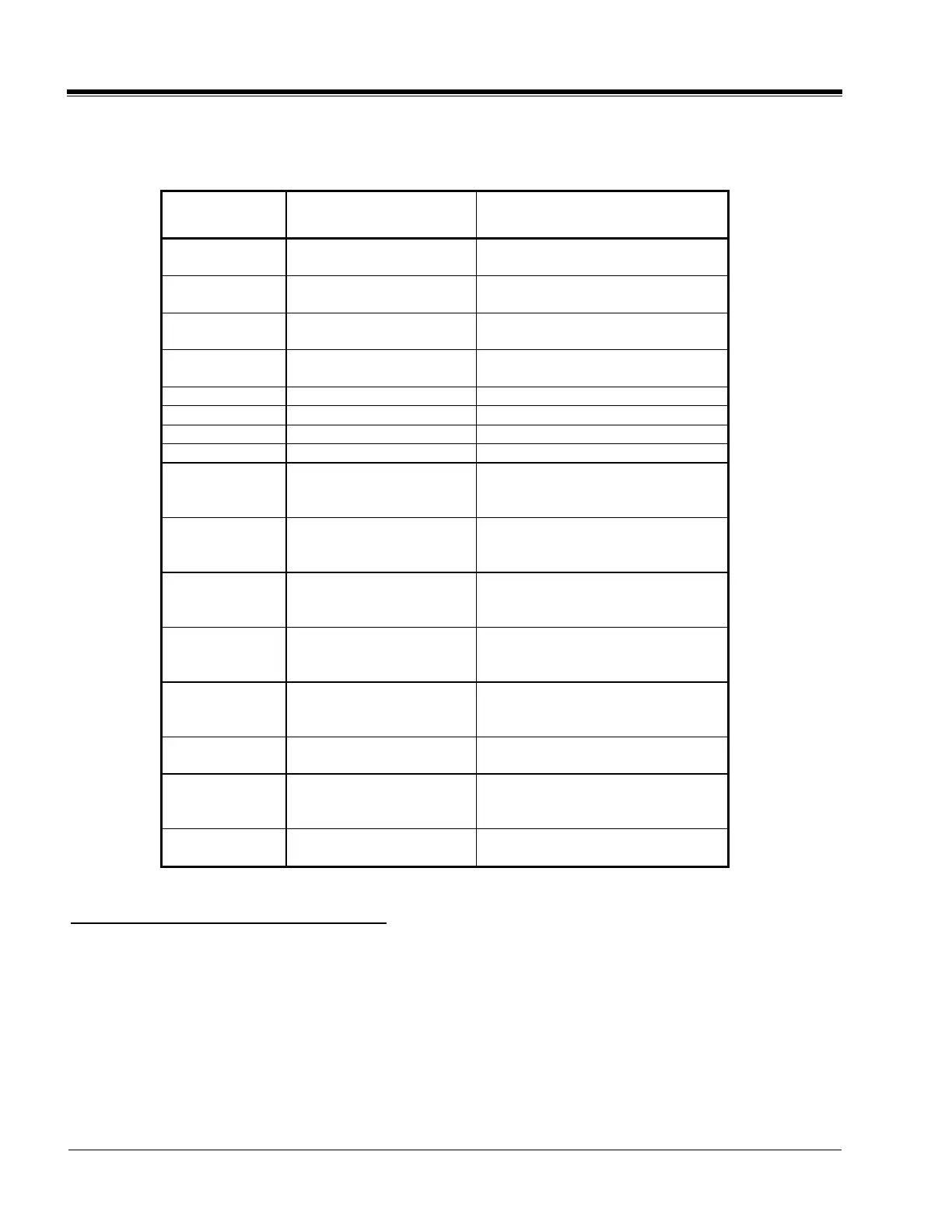
Fault Codes for Status LED
Blink Code Reason for Fault Corrective Action
21
Left Joystick X axis
Voltage out of range
Check Joystick and wires
22
Left Joystick Y axis
Voltage out of range
Check Joystick and wires
23
Right Joystick X axis
Voltage out of range
Check Joystick and wires
24
Right Joystick Y axis
Voltage out of range
Check Joystick and wires
25 Left X axis No cal Recalibrate the Joysticks
26 Left Y axis No cal Recalibrate the Joysticks
27 Right X axis No cal Recalibrate the Joysticks
28 Right Y axis No cal Recalibrate the Joysticks
31
Stage 1 Down/Stage 2
Down Output Open or
Short Circuit
Check valve coil and wires
32
Proportional Unloader
Output Open or Short
Circuit
Check valve coil and wires
33
Head Down/Swing Right
Output Open or Short
Circuit
Check valve coil and wires
34
Head Up/Swing Left
Valve Output Open or
Short Circuit
Check valve coil and wires
35
Cutter Head Motor Valve
Output Open or Short
Circuit
Check valve coil and wires
36
LED Output Open or
Short Circuit
Check valve coil and wires
37
Stage 1 Up/Stage 2 Up
Output Open or Short
Circuit
Check valve coil and wires
38
Relay Driver Output
Open or Short Circuit
Check relay and wires
How to interpret the “BLINK CODE”:
On the bottom of the Controller Box, locate two (2) LED’s; one Red; one Green. Whenever the red LED
lights up you may see the following “BLINKS”:
(2) Red “BLINKS” – pause – (1) Red “BLINK” = “BLINK CODE” 21
(3) Red “BLINKS” – pause – (6) Red “BLINKS” = “BLINK CODE” 36
ETC.
Now check “Reason for Fault” and “Corrective Action” opposite the corresponding “BLINK CODE”.