16
www.evolutionpowertools.com
45°
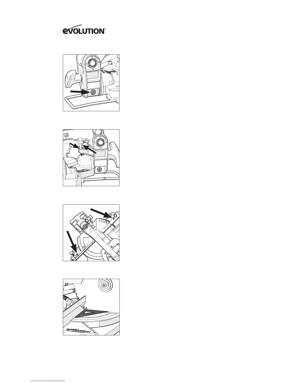
Bevel Stop Adjustment
• Loosenthebevellockinghandleandtiltthecuttinghead
completely to the left until it rests against the 45°
stop.
• Useasetsquare(avoidingtheTCTtipsofthebladeteeth),
check that the blade is at 45°
to the table.
• Ifthesawbladeisnotinexactalignmentadjustment
is necessary.
•Returnthecuttingheadtoitsuprightposition.
• Loosenthelocknutonthe45°
bevel adjustment screw with
a 10mm spanner and 3mm Hex key (Not supplied).
• UsetheHexkeytoadjusttheadjustmentscrewinorout
as required (Fig. 11).
• Tiltthecuttingheadtothe45°
setting and recheck for
alignment with the set square.
• Repeattheabovestepsuntilthecorrectangularalignment
is achieved.
• Tightentheadjustmentscrewlocknutsecurelyonce
alignment is achieved.
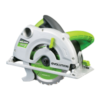
CUTTING HEAD TRAVEL
Cutting Head Downward Travel Adjustment
To prevent the blade from contacting any part of the machines
metal base the downward travel of the cutting head can be
adjusted. Lower the cutting head and check for any blade
contact with the machines base.
If the downward travel of the cutting head needs to be adjusted:
• Loosenthelocknutonthedownwardtravelstopscrewwith
a 10mm spanner (Not supplied) (Fig. 12A).
• Turntheadjustingscrew(Fig. 12B) out (counter-clockwise)
with a 5mm Hex key (Not supplied) to decrease the
downwards travel of the cutting head.
• Turntheadjustingscrewin(clockwise)toincreasethe
downwards travel of the cutting head.
• Tightentheadjustmentscrewlocknutwhensatisfactory
downward travel of the cutting head is achieved.
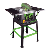
FENCE ALIGNMENT
The fence must be aligned at 90°
(square) to a correctly
installed blade. The rotary table must be set at 0° mitre angle.
Note: The fence is fastened to the machines base with two
socket head Hex screws positioned at either end of the fence
in elongated slots (Fig. 13).
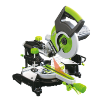
• Ensurethatthecuttingheadisinthelockeddownposition
with the latching pin fully engaged in its socket (Fig. 16).
• Placeasetsquareonthetablewithoneshortedge
against the fence and the other short edge against
the blade (avoiding the TCT tips of the blade teeth) (Fig. 14).
• Repeatonbothsidesoftheblade.
Fig. 11
Fig. 12A + 12B
Fig. 13
Fig. 14
A
B