19
www.evolutionpowertools.com
EN
Positive stops are provided at 45°, 30°, 22.5°, 15°, and 0°
to both the right hand and left hand sides.
• Loosenthemitrelockingscrew(Fig. 20) by turning
it anti-clockwise.
• Turntherotarytabletothedesiredangle.Amitreangle
protractor scale is incorporated into the rotary table
to aid setting.
• Tightenthemitrelockingscrewwhenthedesiredangleis
achieved.
WARNING: It is important (and good practice) to tighten the
mitre locking screw even if a positive stop has been selected.
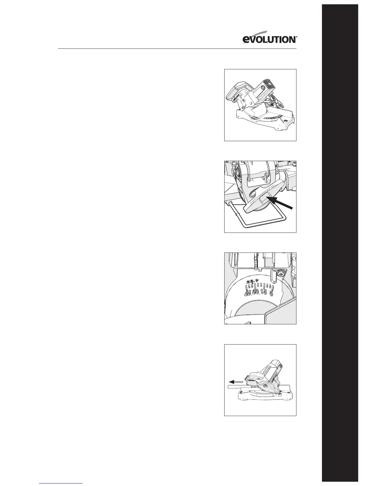
BEVEL CUTTING TILTING THE CUTTING HEAD
A bevel cut (Fig. 21) is made with the rotary table set at
0° mitre angle.
Note: To provide clearance for the moving cutting head and
to accommodate the path of the blade, it may be necessary
to adjust the upper section of the fence. (See Page 16)
The cutting head can be tilted from the normal 0°
(perpendicular position) to a maximum angle of 45°
from the perpendicular to the left hand side only.
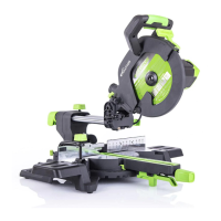
To tilt the cutting head to the left:
• Loosenthebevellockingscrew(Fig. 22).
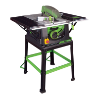
• Tiltthecuttingheadtotherequiredangle.Aprotractor
scale is provided as an aid to setting (Fig 23).
• Tightenthebevellockingscrewwhenthedesiredangle
has been selected.
When cutting is completed:
• ReleasetheON/OFFtriggerswitch,butkeepyourhands
in position and allow the blade to completely stop.
• Allowthecuttingheadtorisetoitsupperposition,
with the lower blade guard completely deployed
before removing your hand(s).
• Returnthecuttingheadtotheperpendicularposition.
• Tightenthebevellockingscrew.
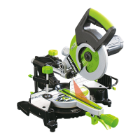
(8.7) COMPOUND CUTTING (Fig. 24)
A compound cut is a combination of a mitre and bevel cut
employed simultaneously. When a compound cut is required,
select the desired bevel and mitre positions as previously
described. WARNING: Always check that the path of the
blade does not interfere with the machines fence or any other
parts of the machine. Conduct a ‘dry run’ with the machined
disconnected from the power source.
Adjust the upper left hand section of the fence if necessary.
Fig. 21
Fig. 22
Fig. 23
Fig. 24