18
www.evolutionpowertools.com
CHECKING AND SETTING OF BEVEL ANGLES
WARNING: Before making any adjustments ensure that the
machine is disconnected from the power supply.
Note: While all angular settings have been factory set,
checking and adjustment may be required as a consequence of
normal operational wear and tear.
Note: To check and adjust the bevel angles the machine must
be in mitre saw configuration.
0˚ BEVEL ANGLE
At 0˚ Bevel Angle the blade should be perpendicular and at
exactly 90˚ to the Rotary Table. An accurate engineers square
(not supplied) is needed to check the 0˚ Bevel Angle.
To check:
• Ensure that the cutting head is in the vertical position,
against its stop with the bevel pointer indicating 0˚ bevel
angle.
• Tighten the bevel lock handle.
• Lower the cutting head to its lowest position. Lock in place
using head locking pin and manually raise lower blade
guard.
• The engineers square can now be used to check the angle
between the blade and the rotary table.
If adjustment is required:
Note: The cutting head will need to be tilted to gain access to
the 0˚ bevel stop adjustment screw.
• Loosen slightly the 0˚ bevel stop adjustment screw locknut.
(Fig. 22)
• Use an allen key to turn the bevel stop screw clockwise or
counterclockwise as required.
• When exact alignment between the
blade and rotary table is achieved, tighten the locknut.
45˚ BEVEL ANGLE
The 45˚ bevel angle can be checked in a similar manner to the
0˚ bevel angle. An accurate 45˚ engineers set square
(not supplied) will be required.
To check:
• Ensure that the cutting head is tilted to the 45˚ position,
against its stop, with the bevel pointer indicating
45˚ bevel angle.
• Tighten the bevel lock handle.
• Lower the cutting head to its lowest position. Lock in place
using head locking pin and manually raise lower blade
guard.
• Use the engineers 45˚ set square to check the angle of
between the blade and the rotary table.
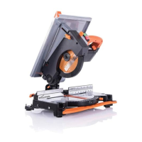
Fig. 22
 Loading...
