16
www.evolutionpowertools.com
• Repeat the above steps until the correct angular alignment is
achieved.
• Tighten the adjustment screw locknut securely once alignment is
achieved.
CUTTING HEAD TRAVEL
Cutting Head Downward Travel Adjustment
To prevent the blade from contacting any part of the machines metal
base the downward travel of the cutting head can be adjusted. Lower
the cutting head and check for any blade contact with the machines
base.
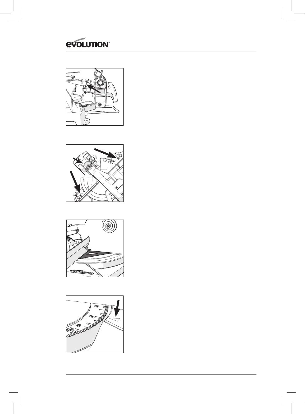
If the downward travel of the cutting head needs to be adjusted:
• Loosen the locknut on the downward travel stop screw with a
10mm spanner (Not supplied) (Fig. 12A).
• Turn the adjusting screw (Fig. 12B) out (counter-clockwise) with a
5mm Hex key (Not supplied) to decrease the downwards travel of
the cutting head.
• Turn the adjusting screw in (clockwise) to increase the downwards
travel of the cutting head.
• Tighten the adjustment screw locknut when satisfactory
downward travel of the cutting head is achieved.
FENCE ALIGNMENT
The fence must be aligned at 90°
(square) to a correctly installed
blade. The rotary table must be set at 0° mitre angle.
Note: The fence is fastened to the machines base with two socket
head Hex screws positioned at either end of the fence in elongated
slots (Fig. 13).
• Ensure that the cutting head is in the locked down position with
the latching pin fully engaged in its socket (Fig. 16).
• Place a set square on the table with one short edge
against the fence and the other short edge against
the blade (avoiding the TCT tips of the blade teeth) (Fig. 14).
• Repeat on both sides of the blade.
• If adjustment is necessary, loosen the two fence attachment screws
using a 5mm Hex key (Not supplied).
• Re-position the fence in its elongated slots until alignment is
achieved.
• Securely tighten the socket head Hex screws.
MITRE ANGLE SCALES & POINTER
Note: There are dual mitre angle scales cast into the RH (Right Hand)
side of the rotary table. A small pointer machined into the machines
base indicates the angle selected (Fig. 15).
FINAL ADJUSTMENT CHECKS
With the machine switched OFF and disconnected from the mains
supply carry out the following (when all adjustments have been
made);
• Set the machine at each of the maximum settings.
• Lower the blade to its lowest position and rotate the blade by
hand, (it is advisable to wear gloves whilst doing this), and ensure
Fig. 13
Fig. 14
A
Fig. 12A + 12B
B
Fig. 15