16
www.evolutionpowertools.com
Some further minor assembly is required to commission this
machine.
WARNING: This machine is heavy. Enlist competent help when
removing this machine from its packaging.
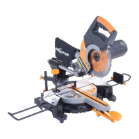
DEPLOYING THE LEGS
The legs are stored underneath the machines main body.
• Releasetheretaininglatch(Fig 13).
• Deploythelegs.
• Ensurethatthelegsaresecuredintotheirserviceposition.
• Thelatchmustdeployandlockthelegssecurelyintheir
service position.
Note: This machine is heavy. Competent help should be
enlisted when moving this machine. Competent help may also
be required when deploying the leg assembly and/or storing
the leg assembly underneath the machine.
THE RIVING KNIFE
The Riving Knife is a very important component, and must be
tted correctly.
The Riving Knife has two functions:
• Itpreventsthework-piecefrombindingasitpassesthrough
the blade.
• Itprovidesasuitableconnectionpointforthebladeguard.
To t and/or check the Riving Knife:
WARNING: Ensure that this procedure is only carried out with
the machine disconnected from the mains supply.
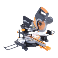
• RemovetheTableAccessPlatebyturningthexingscrew
¼ of a turn. Lift the Access Plate from the machine (Fig. 14).
Carefully store this component for later use.
• Raisethebladetoitshighestposition-Seepage19
‘RAISING/LOWERING THE BLADE’ section.
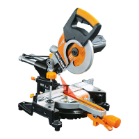
• LoosentheRivingKnifexingboltbyseveralturnsandraise
it to its highest point (Fig. 15).
• SlidetheRivingKnife(itisslottedforconvenience)between
the xing plate and mounting block (Fig. 15). Ensure that the
mounting blocks projecting lugs engage with the slot in the
Riving Knife.
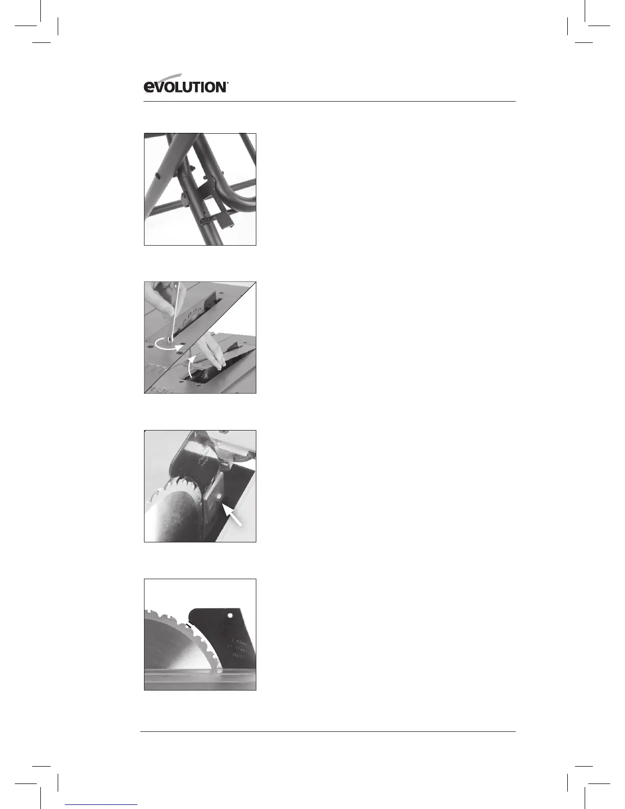
• AdjusttheRivingKnifesothatitisbetween3–5mmfrom
the saw blade. The tip of the riving knife shall not be lower
than 5mm from the tooth peak. (Fig. 16).
• Whencorrectalignmentisachievedtightenthexingbolt.
• Checkthesawbladerotatesfreelyandteetharewithin
3 - 5mm of the Riving Knife.
• Re-installtheTableAccessPlate.
Fig. 13
Fig. 16
Fig. 14
1.
2.
3 - 5mm
Fig. 15