18
www.evolutionpowertools.com
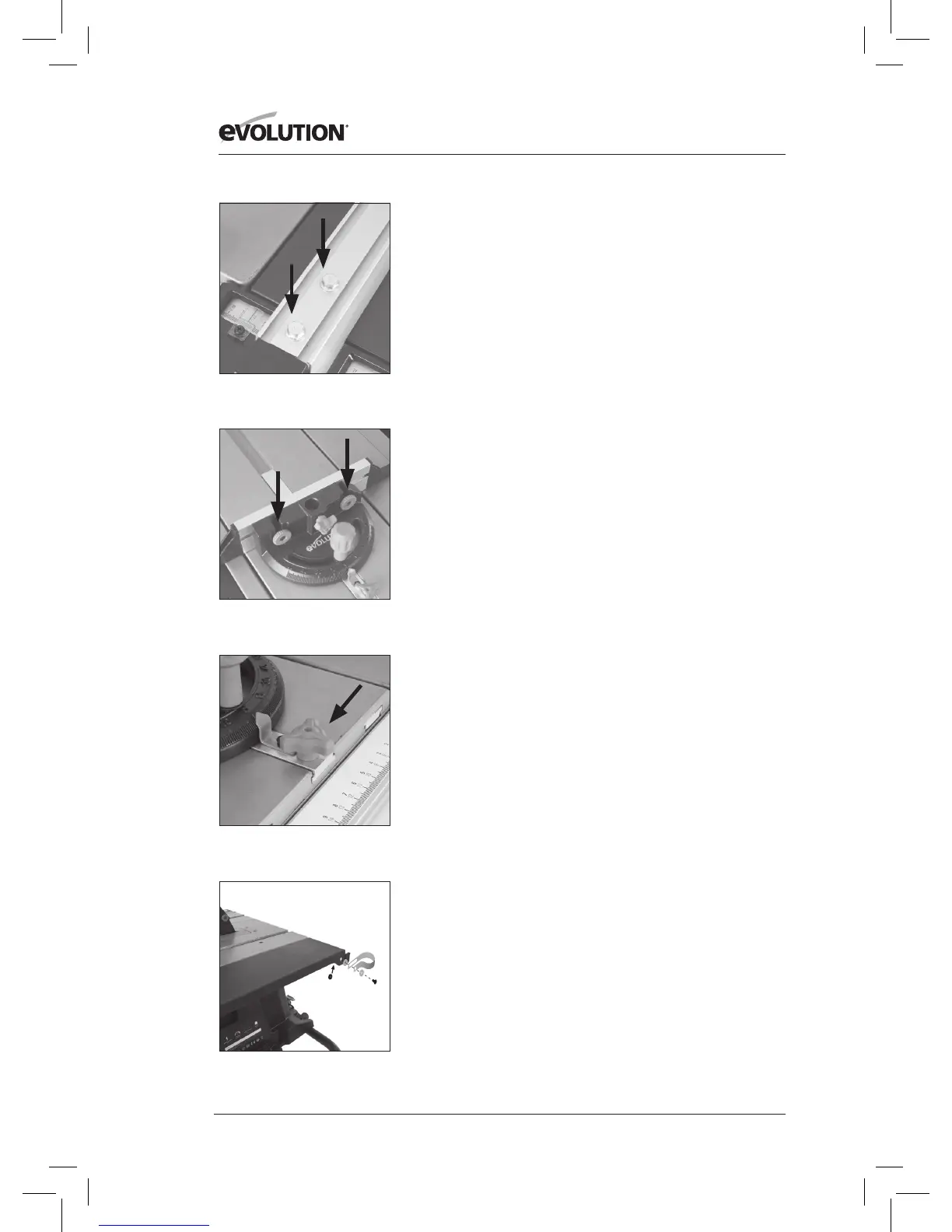
CHECKING/ADJUSTING THE RIP FENCE
When the Rip Fence has been attached to the machine, the Rip
Fence should be checked to ensure that it lies parallel to the blade.
• Raisethebladetoitsfullheight.
• Restastraight-edgeorsimilaragainsttheblade.
• BringtheRipFenceuptothestraight-edgeand
check for parallelism.
• Ifadjustmentisneeded,gainaccesstothetwohexheaded
screws located on the Rip Fence (Fig. 21).
• Loosenthesescrewsslightlyusingasuitablewrench,and
adjust the fence as required.
• Tightenandre-checktheRipFencewhencorrectalignment
has been achieved.
• Lowertheblade.
THE MITRE GAUGE
The Mitre Gauge labelled 10 has an adjustable Face Plate and
provision for a Hold Down Clamp labelled 11.
• InserttheHoldDownClampintothesocketintheMitre
Gauges main body and tighten the locking screw.
• AttachtheFacePlateoftheMitreGauge.
• Slidetheattachmentscrewsthroughthetwo(2)holesin
Mitre Gauges vertical face and secure in place with the
thumb nuts (Fig. 22).
• TheMitreGaugeisusuallyemployedontheLHsideofthe
table and runs in an inverted T slot in the table top.
• TheMitreGaugecanbelockedontotheSlidingCarriageby
screwing the locking screw into a hole located to the front
edge of the Sliding Carriage (Fig 23).
DUST EXTRACTION
• Attachoneendofthehosetothebladeguard.
• Attachthedustextractionhoseclip to the rear of the RH
(right hand) side table extension using the xings labelled
F, H and M (Fig. 24).
• Runthehosethroughthecliptotheportontherearof
the machine.
TRANSPORTING YOUR TABLE SAW
WARNING: Ensure that this procedure is only carried out with
the machine disconnected from the mains supply.
• Ensurethatthemachineisdisconnectedfromthemainssupply
and that the power cord is securely stored on the machine.
• Releasethelatchingpin.
• Graspthetransportationhandle(Fig. 25).
• Gentlyandslowlyliftthehandle,allowingthemachineto
maintain balance and stability.
• Wheelthemachinetoitsnewlocation
.
Fig. 24
Fig. 21
Fig. 22
Fig. 23