Operation
AdjustingtheCuttingHeight
Therearwheelsareadjustedtogetherwithaheight
adjustmentrodlocatedonthemowerhousingby
theleftrearwheel.Thefrontwheelsareadjusted
separatelybyremovingthefrontwheelshaft
assemblies,adjustingtheheight,andthenreplacing
theshaftassemblies.Thecuttingheightcanbe
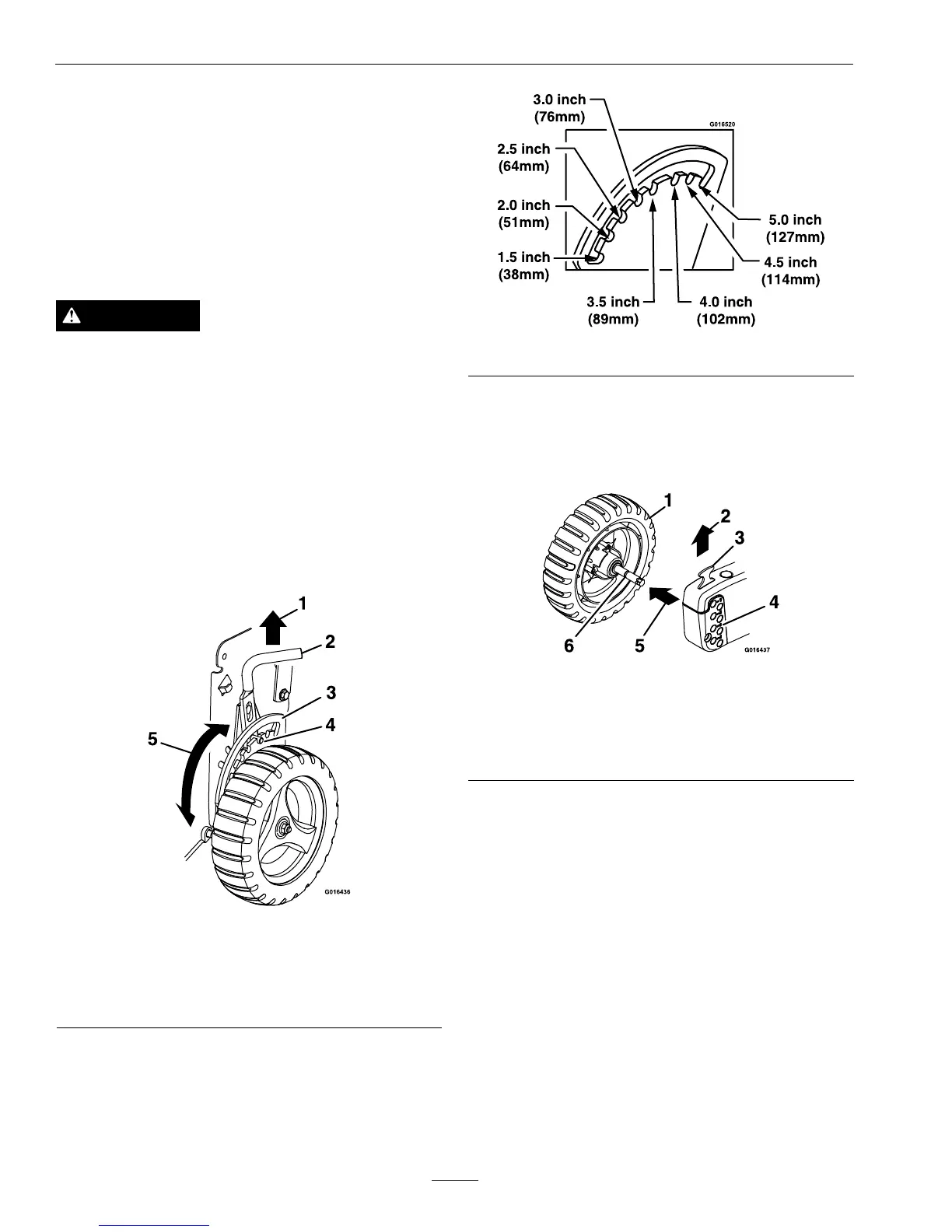
adjustedfrom11/2inches(38mm)to5inches(127
mm)in1/2inch(12.7mm)increments.
WARNING
Adjustingthecuttingheightleverscouldbring
yourhandsintocontactwithamovingblade.A
movingbladecancauseseriousinjury.
•Stoptheengineandwaitforallmovementto
stopbeforeadjustingthecuttingheight.
•DoNotputyourngersunderthehousing
whenadjustingthecuttingheight.
•RearWheelAdjustment:
1.Pullthewheelheightadjustmentrodupward
toreleasethepinfromthenotchinthe
adjustmentbracket(Figure10).
Figure10
1.Pullupward4.Pin
2.Wheelheightadjustment
rod
5.Rotatetodesiredsetting
3.Indicator
2.Applydownwardpressureorliftthehousing
torotatetheheightadjustmentbrackettothe
desiredsetting.
3.Releasethewheelheightadjustmentrodtoset
thepinsecurelyinthedesirednotch.
Figure11
•FrontWheelAdjustment
1.Pullupontheheightlockandpullthefront
wheelshaftassemblyoutwardasshownin
Figure12.
Figure12
1.Frontwheelshaft
assembly
4.Frontquadrantblockcut
heights
2.Pullup5.Pulloutward
3.Heightlock
6.Shaftgroove
2.Insertthefrontwheelshaftassemblyintothe
desiredcutheightsettinginthefrontquadrant
block.Lowertheheightlockintothegroove
onthefrontwheelshaft.Pullandpushthe
wheelshaftassemblytomakesureithas
lockedintoplace.
16