Operation
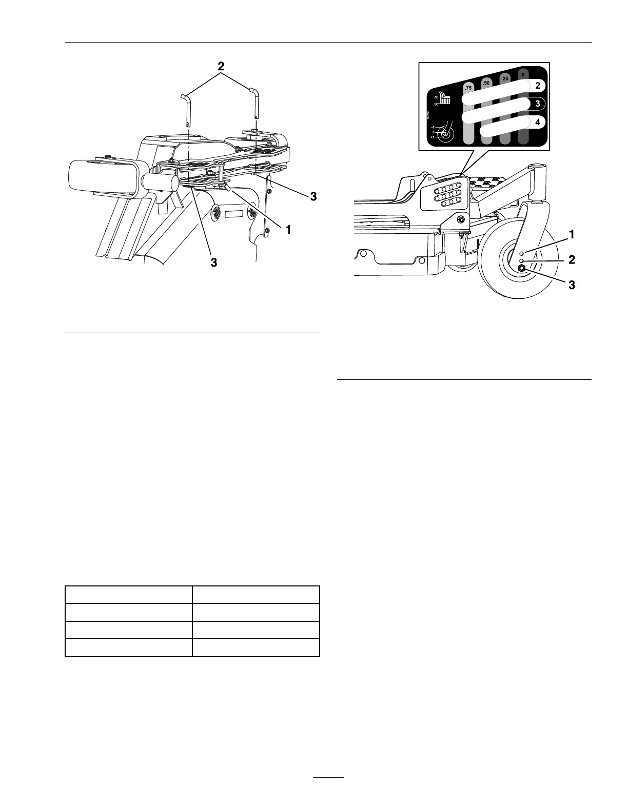
g295443
Figure24
1.Unlockcamlock3.Lynchpin
2.Heightofcutpin
C.Removethelynchpinfromtheheightofcut
pinonboththefrontandrearchannels.
D.Movethewingdecktotheappropriateheight
andreinstalltheheightofcutpinsandlynch
pinsasshowninFigure24.
E.Lockthecamlock.
F.Repeatforotherwingdeck.
7.Ifadditionalheightofcutrangeisdesired,adjust
thefrontandreargaugewheelsonthewingdeck:
A.Removethemountinghardwarefromthe
gaugewheel.
B.Adjustthefrontandreargaugewheelstothe
appropriateholelocation(seethechartbelow
andFigure25)andreinstallthemounting
hardware.
HoleLocationHeightofCutRange
Tophole(-1ondecal)
1–3.5inches(25–89mm)
Middlehole(0ondecal)
2–4.5inches(51–114mm)
Bottomhole(+1ondecal)
3–5.5inches(76–140mm)
g295444
Figure25
1.Tophole(-1ondecal)
2.Middlehole(0ondecal)
3.Bottomhole(+1ondecal)
C.Repeatforotherwingdeck.
AdjustingtheAnti-ScalpRollers
Itisrecommendedtochangetheanti-scalproller
positionwhentheheightofcuthaschanged.
1.Stopthemachineandmovethemotioncontrol
leversoutwardtotheneutrallockedposition.
2.DisengagethePTO.
3.Engagetheparkbrake.
4.Stoptheengine,removethekeyandwaitforall
movingpartstostop.
5.Afteradjustingtheheightofcut,adjustthe
anti-scalprollersbyremovingthemounting
hardware.
6.Placetherollersinoneofthepositionsshown
(Figure26).Rollerswillmaintain3/4inch(19
mm)clearancetothegroundtominimizegouging
androllerwearordamage.
43

 Loading...