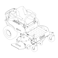
Maintenance
Voltage
Reading
Percent
Charge
Maximum
Charger
Settings
Charging
Interval
12.6or
greater
100%
16volts/7
amps
No
Charging
Required
12.4–12.675–100%
16volts/7
amps
30Minutes
12.2–12.450–75%
16volts/7
amps
1Hour
12.0–12.225–50%
14.4volts/4
amps
2Hours
11.7–12.00–25%
14.4volts/4
amps
3Hours
11.7orless
0%
14.4volts/2
amps
6Hoursor
More
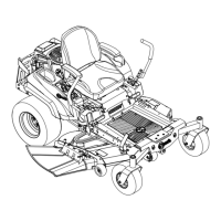
4.Whenthebatteryisfullycharged,unplug
thechargerfromtheelectricaloutlet,then
disconnectthechargerleadsfromthebattery
posts(Figure29).
Figure29
1.Negativebatterypost
3.Red(+)chargerlead
2.Black(-)chargerlead
4.Positivebatterypost
Note:DoNotrunthemachinewiththebattery
disconnected,electricaldamagemayoccur.
InstallingtheBattery
1.Positionthebatteryinthetraywiththeterminal
poststowardtheoperatingposition(Figure28).
2.Installthepositive(red)batterycabletothe
positive(+)batteryterminalusingthefasteners
removedpreviously.
3.Installthenegativebatterycabletothenegative
(-)batteryterminalusingthefastenersremoved
previously.
4.Slidetheredterminalbootontothepositive(red)
batterypost.
5.Securethebatterywiththestrap(Figure28).
ServicingtheFusesand
Relay
Theelectricalsystemisprotectedbyfuses.Itrequires
nomaintenance;however,ifafuseblows,check
thecomponent/circuitforamalfunctionorshort.
Thereisalsoareplaceablerelay/snexttothefuse.
RefertoyourPartsmanualforcorrectreplacement
components.
FuseBlock:
•Mainfuse:25ampfuse,blade-type
•ChargeCircuit:20ampfuse,blade-type
•Auxiliarycircuit:15ampfuse,blade-type
•Diode:TVS
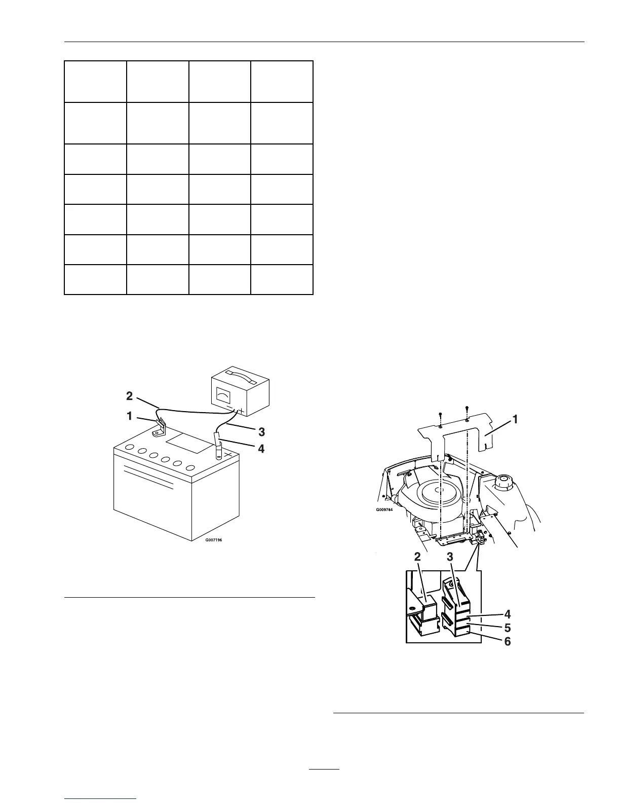
1.Raisetheseattogainaccesstothefuseholder
(Figure30).
Figure30
1.Cover4.Charge–20amp
2.Relay5.Main–25amp
3.Auxilliary–15amp6.Diode
2.RemovecoverasshowninFigure30.
3.Toreplaceafuse,pulloutonthefusetoremoveit
37