Operation
3.Movetheseattothedesiredpositionand
tightenbolts.
4.Tiptheseatbacktotheclosedposition.
•S-SeriesUnits:
1.Pushtheadjustmentlevertowardsthecenter
ofthemachinetoreleasetheseatadjuster
track(Figure19).
g237277
Figure19
1.Adjustmentlever
2.Movetheseattothedesiredpositionand
releasethelevertolockinthatposition.
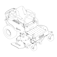
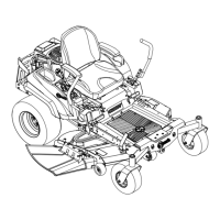
ChangingtheSeatRide
Suspension
Thenumberofseatspringscanbechangedto
maximizeridercomfort.Morespringsshouldbeused
withheavieroperatorsandonroughterrain.Fewer
springsshouldbeusedwithlighteroperatorsand
whenmowingsmooth,wellestablishedlawns.Always
keepthenumberofspringsontheleftandrightside
thesamewhenaddingandremovingsprings.
g237291
Figure20
1.Bolt3.Nut
2.Spring
4.Additionalmounting
holes
Uptovespringscanbesecuredtotheseatboxwith
anutandbolt,seeFigure20.
RefertoyourPartsManualforspringandhardware
partnumbers.
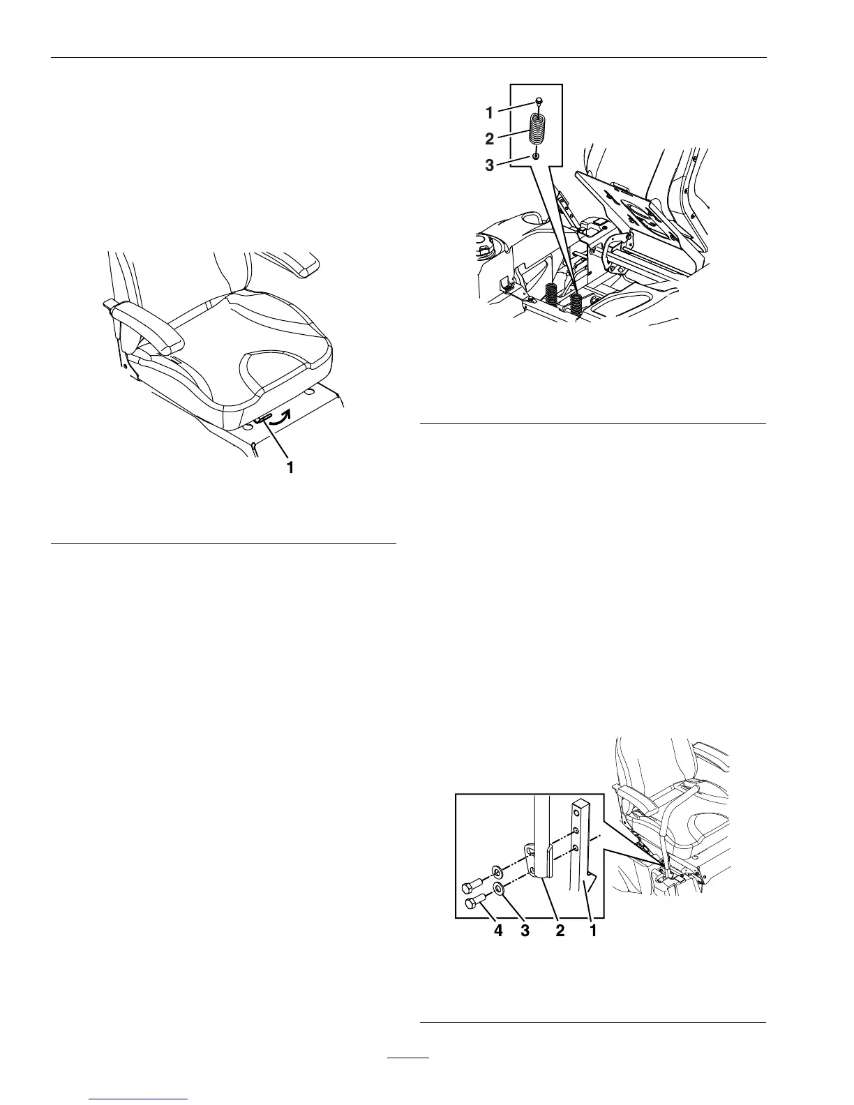
AdjustingtheMotionControl
Levers
AdjustingtheHeight
Themotioncontrolleverscanbeadjustedhigheror
lowerformaximumoperatorcomfort.
1.Removethehardwareholdingthecontrolleverto
thecontrolarmshaft(Figure21).
g237376
Figure21
1.Controlarmshaft
3.Washer
2.Controllever
4.Bolt
30
 Loading...