Maintenance
g017617
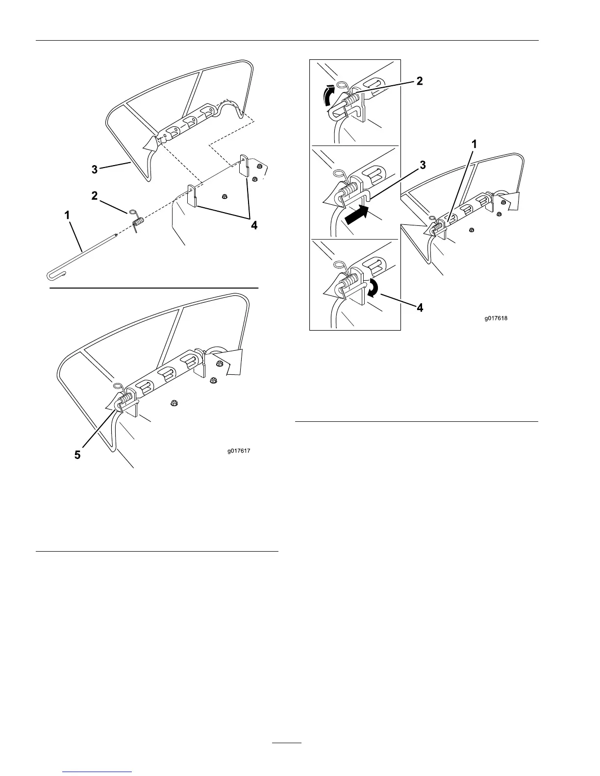
Figure81
1.Rod4.Deckbrackets
2.Spring5.Springinstalledoverthe
rod
3.Deectorassembly
2.Positionthenewdischargedeectorassembly
withthebracketendsbetweenthewelded
bracketsonthedeckasshowninFigure81.
3.Installthespringontothestraightendofthe
rod.Positionthespringontherodasshown
insotheshorterspringendiscomingfrom
undertherodbeforethebendandgoingover
therodasitreturnsfromthebend.
4.Lifttheloopendofthespringandplace
itintothenotchonthedeectorassembly
bracket(Figure82).
g017618
Figure82
1.Rodandspring
assemblyinstalled
3.Rod,shortend,moved
behindmowerbracket
2.Loopendofthespring
installedintothenotchin
thedeectorbracket
4.Shortend,retainedby
mowerbracket.
5.Securetherodandspringassemblybytwisting
itsotheshortendoftherodcanbeplaced
behindthefrontbracketweldedtothedeck
(Figure82).
Important:Thegrassdeectormustbe
springloadedinthedownposition.Lift
thedeectoruptotestthatitsnapstothe
fulldownposition.
64
 Loading...