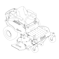
Figure48
50InchDecks
1.Bladessidetoside
3.Outsidecuttingedges
2.Sailareaofblade4.Measurefromthetip
ofthebladetotheat
surfacehere
5.Measurebetweentheoutsidecuttingedgesand
theatsurface(Figure47andFigure48).Ifboth
measurementsarenotwithin3/16inch(5mm),
anadjustmentisrequired;continuewiththis
procedure.
6.Supporttheweightofmowerdeckbyplacing
woodblocksundertheedgesofthedeck.
Note:Avoidplacingthesupportsunderany
anti-scalprollersifpresentonthedeck.
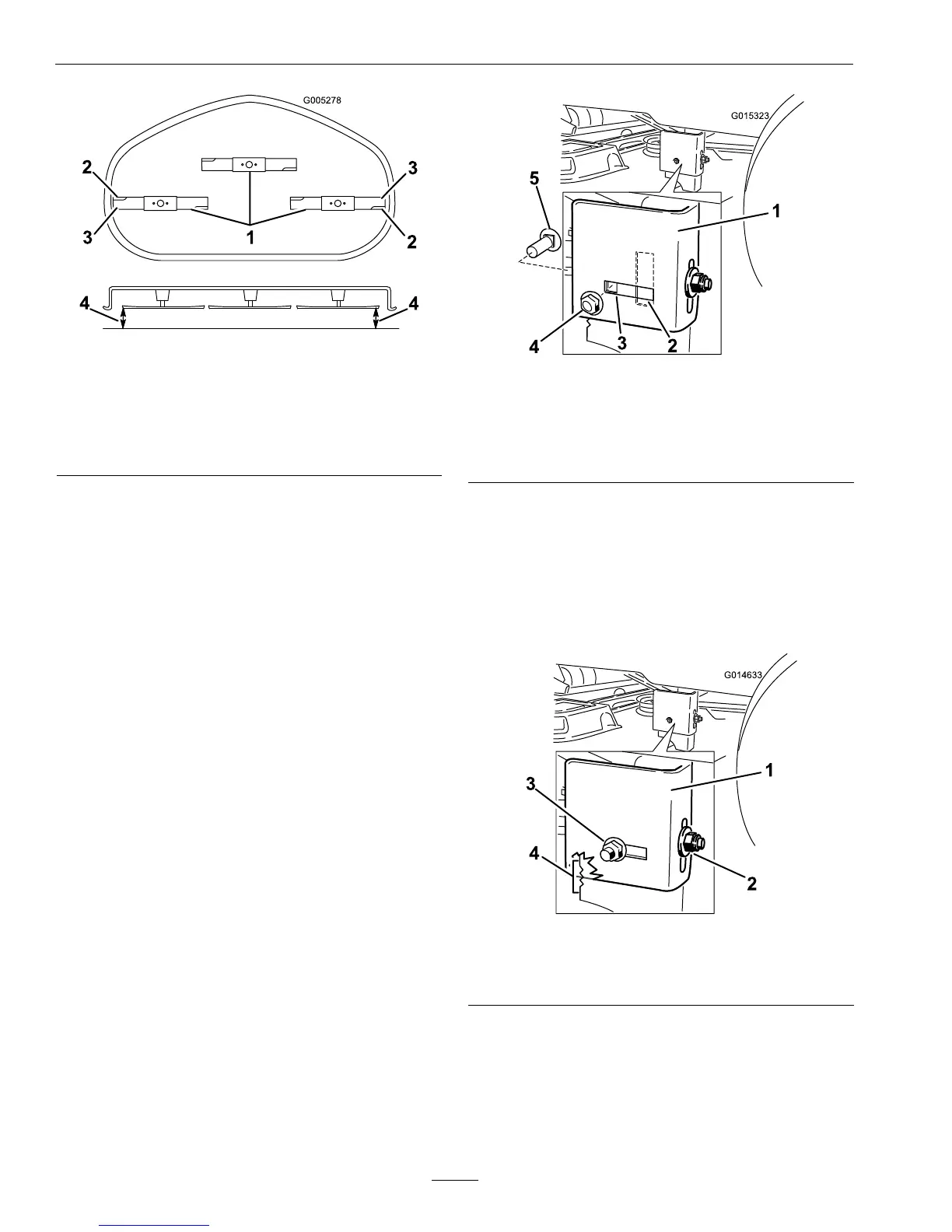
7.Movetotheleftsideofthemachine.Remove
thesidecarriageboltandlockingnutfromthe
xedpositionandinstallitintotherear,slotted
positionandleaveitslightlyloose(
Figure49).
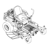
Figure49
1.Hangerbracket
4.Sidelockingnut
2.Slottedadjustment
position
5.Sidecarriagebolt
3.Fixedposition
8.Loosenthesidelockingnutonthehangerbracket
justenoughtoallowthehangertobeadjusted
(Figure50).Usethenotchesonthewelded
brackettomeasuretheamountofadjustment.
Eachnotchsurfaceisequivalentto1/16ofan
inch.Adjusttheheightofthemowerdecktothe
desiredheight.
Figure50
1.Hangerbracket
3.Sidelockingnut
2.Rearlockingnut4.Adjustmentnotches
9.Stopthedeckattheadjustedpositionandtighten
thesidelockingnutonthehangerbrackettohold
46