MAINTNANCE MANUAL EXTRA 300/SC
PAGE DATE: 1. August 2014 CHAPTER 53
PAGE 15
53-00-04 Bottom Fuselage Cover
Removal
1 Remove engine cowling as per Chapter 71, the landing gear
cuffs and main fuselage cover in accordance with this chap-
ter.
2 Pull the plug of the optional OAT sensor wiring, if appli-
cable.
3 Disconnect the antenna wirings.
4 Remove bottom fuselage cover by removing the attachment
screws.
Installation
I M P O R T A N T The cockpit area must be thoroughly sealed and thus
separated from the engine compartment. Gases or flu-
ids could get into the cockpit area.
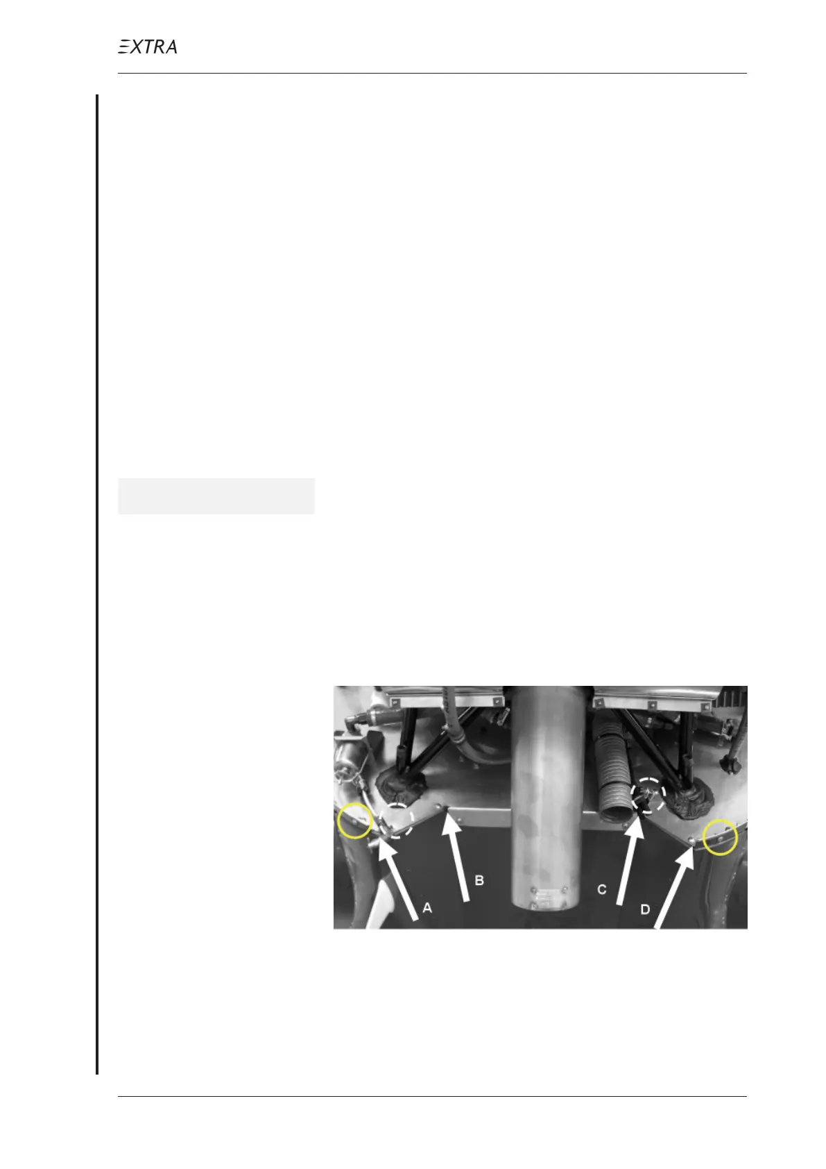
Critical areas to be observed are the following:
Position A and D of Figure 7, where different parts converge
(firewall, aluminium profile, bottom fuselage cover and
exhaust area covering sheet). Position B and C, where a bent
corner ends in a bore hole.
Figure 11 Forward View on Bottom Side Firewall
1 Position the bottom fuselage cover in its original position.
2 Plug the optional OAT sensor wiring, if applicable.
3 Connect the antenna wirings.