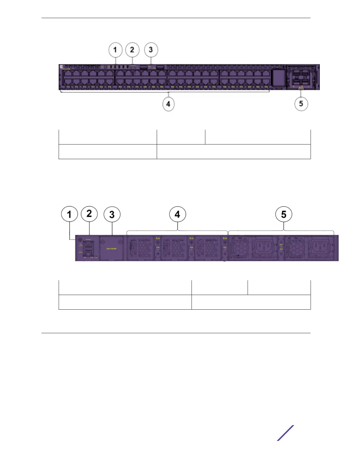
Figure 1: VSP 4900 Series Switch: Front Panel
1 = Mode Button and System LEDs 3 = USB A ports 5 = VIM slot, shown with VIM installed
2 = USB micro B management port 4 = Access ports
The rear panel of the ExtremeSwitching VSP4900-48P switch includes:
•
3 fan modules
•
2 unpopulated PSU slots
•
RJ-45 console and management ports
Figure 2: VSP 4900 Series Switch: Rear Panel
1 = Grouding lug 3 = SSD slot 5 = Power supplies
2 = RJ45 console and management ports 4 = Fan modules
VSP License Options
For information about licensing options for VOSS, see Administering VSP Operating System Software.
Overview of the VSP 4900 Series Switch
VSP 4900 Series Switches: Hardware Installation Guide 11
 Loading...