12 Monitoring the Switch
VSP 4900 Switch LEDs
The following topics help you monitor the status of the switch/appliance as it is running.
VSP 4900 Switch LEDs
ExtremeSwitching VSP 4900 Front Panel Port LEDs, as described in the following table:
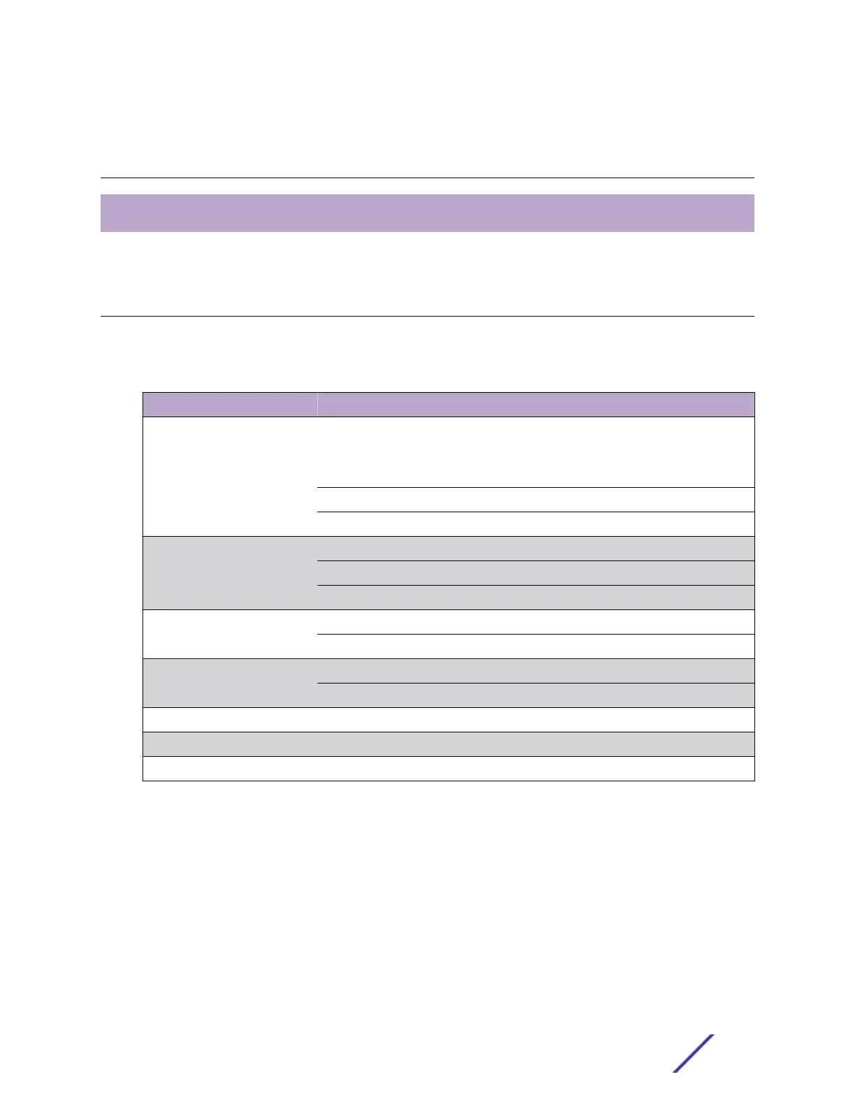
Table 16: VSP 4900 Port LEDs
LED Color/State Port State
SYStem status LED
(Legacy MGMT function)
Green Flash slowly POST Passed,
normal operation, blinks on standalone switch, stack master,
and backup nodes in a stack;
o for standby nodes in a stack
Green Blinking POST in progress
Amber Blinking POST failed or overheat
PSU status LEDs P1/P2 Green Power On
O Power o and no power attached
Amber Blinking Power supply failures
Fan status LEDS (F1, F2 and F3) Green Normal operation
Amber Blinking Fan failure
Bluetooth Status LED (BT) Green Blinking Bluetooth pairing in progress
Green Bluetooth connected
Locator LED (LOC) Blue Blinking Locator function
Ethernet Port 1-24 or 1-48
VIM5 Port 25-32 or 49-56
The following figure shows the two alternate mode LEDs for VSP 4900 switches: SYS and SPD. The
Mode button is used to cylce through two display modes for the port LEDs. SYS and SPD display modes
will expire after 30 seconds, at which time the port LEDs will revert to the default SYS mode.
VSP 4900 Series Switches: Hardware Installation Guide 57
 Loading...