2-5
ISM 824 Integration Scaling Multiswitcher • Installation
Cabling and RJ-45 connector wiring
It is vital that the Ethernet cables used be the correct type of cable, and that they be
properly terminated with the correct pinout.
Choosing a network cable
Ethernet links use Category (CAT) 3, 4, 5, 5e, or 6, unshielded twisted pair (UTP)
or shielded twisted pair (STP) cables, terminated with RJ-45 connectors. Ethernet
cables are limited to 328' (100 m)
The cable used depends on the network speed. The ISM supports both 10 Mbps
(10Base-T — Ethernet) and 100 Mbps (100Base-T — Fast Ethernet), half-duplex and
full-duplex, Ethernet connections.
• 10Base-T Ethernet requires, at a minimum, CAT 3 UTP or STP cable.
• 100Base-T Fast Ethernet requires, at a minimum, CAT 5 UTP or STP cable.
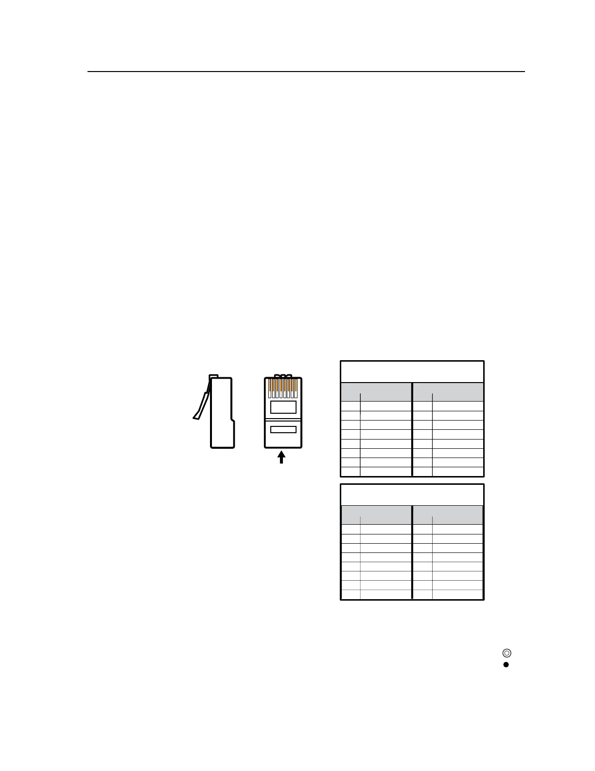
Terminating the network cable
The cable can be terminated as either a patch cable or a crossover cable (figure 2-4)
and must be properly terminated relevant to the application:
•
Patch (straight) cable — Connection of the ISM to an Ethernet hub, router, or
switcher that also hosts a controlling computer.
•
Crossover cable — Direct connection between the ISM and a controlling
computer.
12345678
RJ-45 Connector
Insert
Tw isted
Pair Wires
Pins:
Side View
Straight-through Cable
(for connection to a switch, hub, or router)
End 1 End 2
Pin Wire Color Pin Wire Color
1 white-orange 1 white-orange
2 orange 2 orange
3 white-green 3 white-green
4 blue 4 blue
5 white-blue 5 white-blue
6 green 6 green
7 white-brown 7 white-brown
8 brown 8 brown
Crossover Cable
(for direct connection to a PC)
End 1 End 2
Pin Wire Color Pin Wire Color
1 white-orange 1 white-green
2 orange 2 green
3 white-green 3 white-orange
4 blue 4 blue
5 white-blue 5 white-blue
6 green 6 orange
7 white-brown 7 white-brown
8 brown 8 brown
Figure 2-4 — RJ-45 connector pinout tables
d
Reset button and LED — Pressing this recessed button
causes certain IP functions and Ethernet connection settings
to be reset to the factory defaults. The green LED above the
button blinks a varying number of times to indicate which
reset mode has been entered. See chapter 3, “Operation and Setup” ,
“Resetting the unit with the reset button” section, for information on reset
modes.