Quick Start — ISM 824
Integration Scaling Multiswitcher
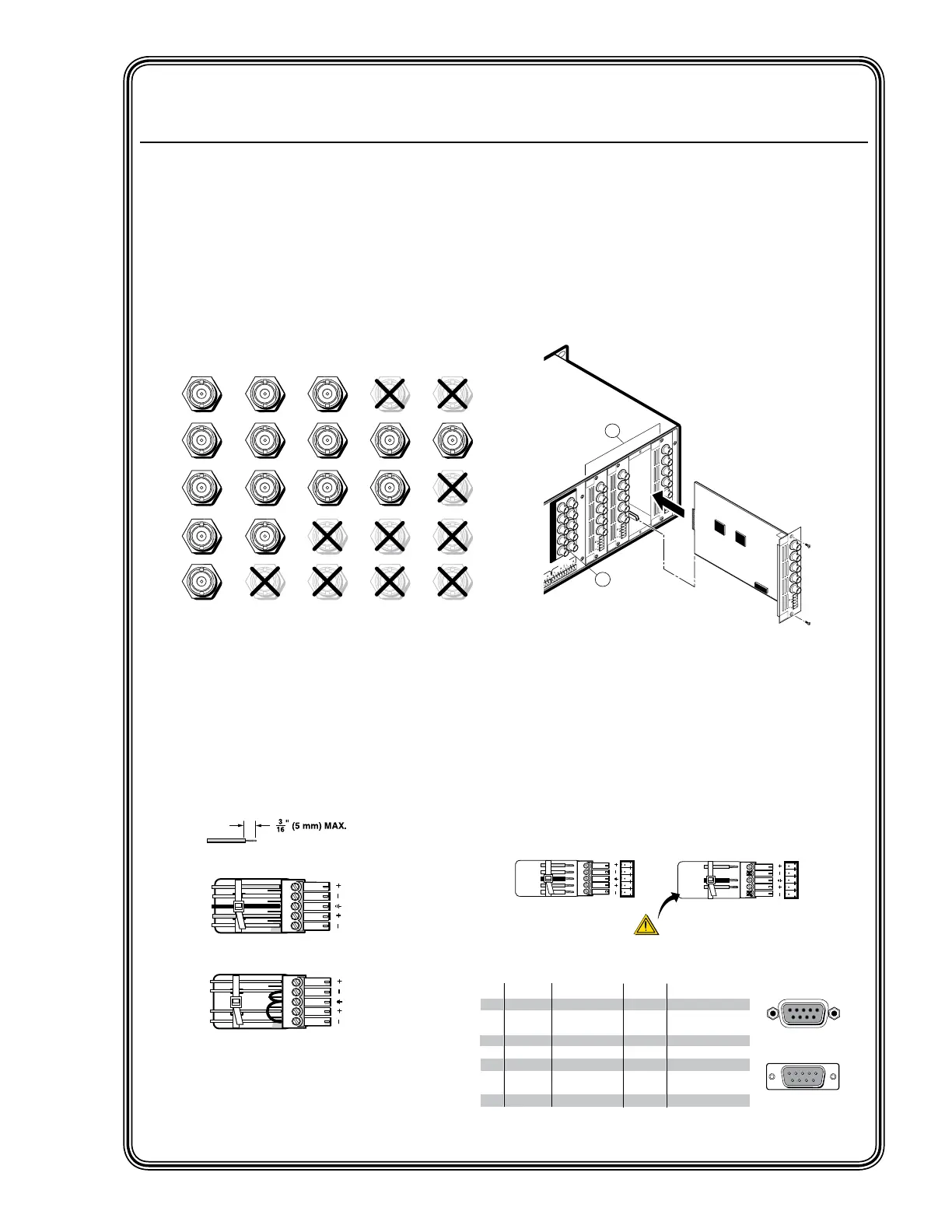
H/HV
RGBHV
Video
RGsB or
Component
Video
S-Video Composite
Video
RGBS
Video
V
H/HV
V
H/HV
V
H/HV
V
H/HV
V
R/R-Y
G/Y
VID
B/C
B-Y
R/R-Y
G/Y
VID
B/C
B-Y
R/R-Y
G/Y
VID
B/C
B-Y
R/R-Y
G/Y
VID
B/C
B-Y
R/R-Y
G/Y
VID
B/C
B-Y
Figure Q-1 — Video format for BNC
connections
Step 4 — Video outputs
a. Pass-through outputs — Connect video
devices to the BNC connectors for outputs
1 and 2. Connect cables as shown in figure
Q-1.
b. Install any optional output boards (see
figure Q-3), and connect the relevant display
device to the BNC connectors on the boards.
See figure Q-1 for cabling format.
Figure Q-3 — Install Output cards
Step 5 — Audio outputs
Connect balanced or unbalanced stereo
audio or mono audio devices to the 5-pin
captive screw output connectors.
Step 6 — Serial ports
a. If desired, connect a control system or
computer to the rear panel RS-232/RS-422
port.
Figure Q-2 — Audio connections
Figure Q-4 — Remote port pin
assignments
Unbalanced Stereo Output
CAUTION
For unbalanced audio, connect the sleeve(s) to
the center contact ground. DO NOT connect the
sleeve(s) to the negative (-) contacts.
Balanced Stereo Output
Tip
Ring
Sleeve(s)
Tip
Ring
L R
Left
Right
Tip
NO GROUND HERE.
Sleeve(s)
Tip
NO GROUND HERE.
L R
Left
Right
RS-232 FunctionPin
1
2
3
4
5
6
7
8
9
—
TX
RX
—
Gnd
—
—
—
—
Not used
Transmit data
Receive data
Not used
Signal ground
Not used
Not used
Not used
Not used
51
9
5
9
6
Female
Male
1
6
RS-422 Function
TX
RX
—
Gnd
—
RX+
TX+
—
Not used
Transmit data (-)
Receive data (-)
Not used
Signal ground
Not used
Receive data (+)
Transmit data (+)
Not used
—
100
-
240
50/60 Hz
1.2A
MA
X.
1
23456 78
2 1 23 45678
1
2
1
INPUTS OUTPUTS
R/R-Y
G/Y
VID
B/C
B-Y
H/HV
V
R/R-Y
G/Y
VID
B/C
B-Y
H/HV
V
PAS
S THRU
INPUT
S
RES
ET
LAN
REMOTE
RS232/RS422
ACT
LINK
OUTPUT
VIDEO
SCALER
70-545-01
3
R/
R-Y
G/Y
B/
B-Y
H/
HV
V
OUTPUT
UNIV.
SCALER
70-544-01
5
R/
R-Y
G/Y
B/
B-Y
H/
HV
V
OUTPUT
PASS
THRU
70-547-01
8
R/
R-Y
G/Y
B/
B-Y
H/
HV
V
Extron
ISM 824
Integration Scaling
Multiswitcher
a
b
Align Output Card with
top and bottom plastic guides
of an open port.
Slide card in and secure
with screws.
R/
R-Y
G/Y
B/
B-Y
H/
HV
V
OUTPUT
7
SCAN
CONV
.
70-546-01
QS-1
ISM 824 Integration Scaling Multiswitcher • Quick Start
Installation
Step 1
Turn off power to the input and output devices,
and remove the power cords from them.
Step 2 — Video inputs
Inputs 1 through 8 — Connect RGB video,
component video, S-video, or composite
video to these female BNC connectors. See
below for format.
Step 3 — Audio inputs
Inputs 1 through 8 — Connect up to eight
stereo or mono audio inputs to the 5-pin
captive screw input connectors. Wire the
connectors as shown below.
Unbalanced audio
Balanced audio
Tip
Ring
Tip
Ring
L R
Sleeves
Do not tin the wires!
Tip
Sleeve
Sleeve
Tip
L R