ATTENTION:
• The installation must always be in accordance with the applicable provisions of
National Electrical Code ANSI/NFPA 70, article 725 and the Canadian Electrical Code
part 1, section 16.
• Cette installation doit toujours être en accord avec les mesures qui s’applique au
National Electrical Code ANSI/NFPA70, article725, et au Canadian Electrical Code,
partie1, section16.
• The power supply shall not be permanently fixed to the building structure or similar
structure.
• La source d’alimentation ne devra pas être fixée de façon permanente à une structure
de bâtiment ou à une structure similaire.
An Extron IPL Pro control processor must also be connected to the same network domain as the
TouchLink Pro touchpanel. See the www.extron.com for a list of suggested models.
The network port has two LEDs. The green LED lights steadily to indicate that the touchpanel is
connected correctly to a network. The yellow LED flashes to indicate that data is being passed to
or from the touchpanel.
E
Mounting holes (4) (TLP Pro 1022M only) (see figure 3) — for wall mounting (see Wall
Mounting on page 18).
F
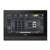
Status light (TLP Pro 1022T only) — can be programmed to provide system feedback.
• Light red or green
• Blink or solidly lit
For information about programming this light, see the Global Configurator Help File.
G
VESA mounting holes (4) (TLP Pro 1022T only)— for use with the Extron LPVM-1 (see
VESA Mounting on page 22).
H
Base attachment hinges (2) (TLP Pro 1022T only)— Secure the base to the touchpanel.
For VESA mounting, remove the base by unscrewing the hinges (see VESA Mounting on
page 22).
TLP Pro 1022 Series • Panel Features 7