Page | 11
14. FEATURES
14.1. POWER
14.1.1. The VPL motor uses 24 volts DC supplied by two 12VDC, 12AH (amp hour) batteries connected in
series. The VPL control voltage uses 12 volts DC supplied by one of those two batteries. The
batteries are charged by a built-in smart charger. Household power (120VAC) is used to operate
the charger and is supplied via an outdoor rated 12’ (standard) power cord.
The AC power cord must be connected to a properly grounded and polarized receptacle.
14.1.2. In the event of a power failure, the VPL is designed to operate approximately 20 cycles on
battery power before recharging the batteries is required.
One “cycle” is the VPL moving up-and-down once or down-and-up once.
14.1.3. The batteries require approximately 6 hours to fully charge if totally discharged.
VPL cycles and recharge times are highly dependent on outside temperatures and loads.
Low temperatures decrease battery performance and increase charging time.
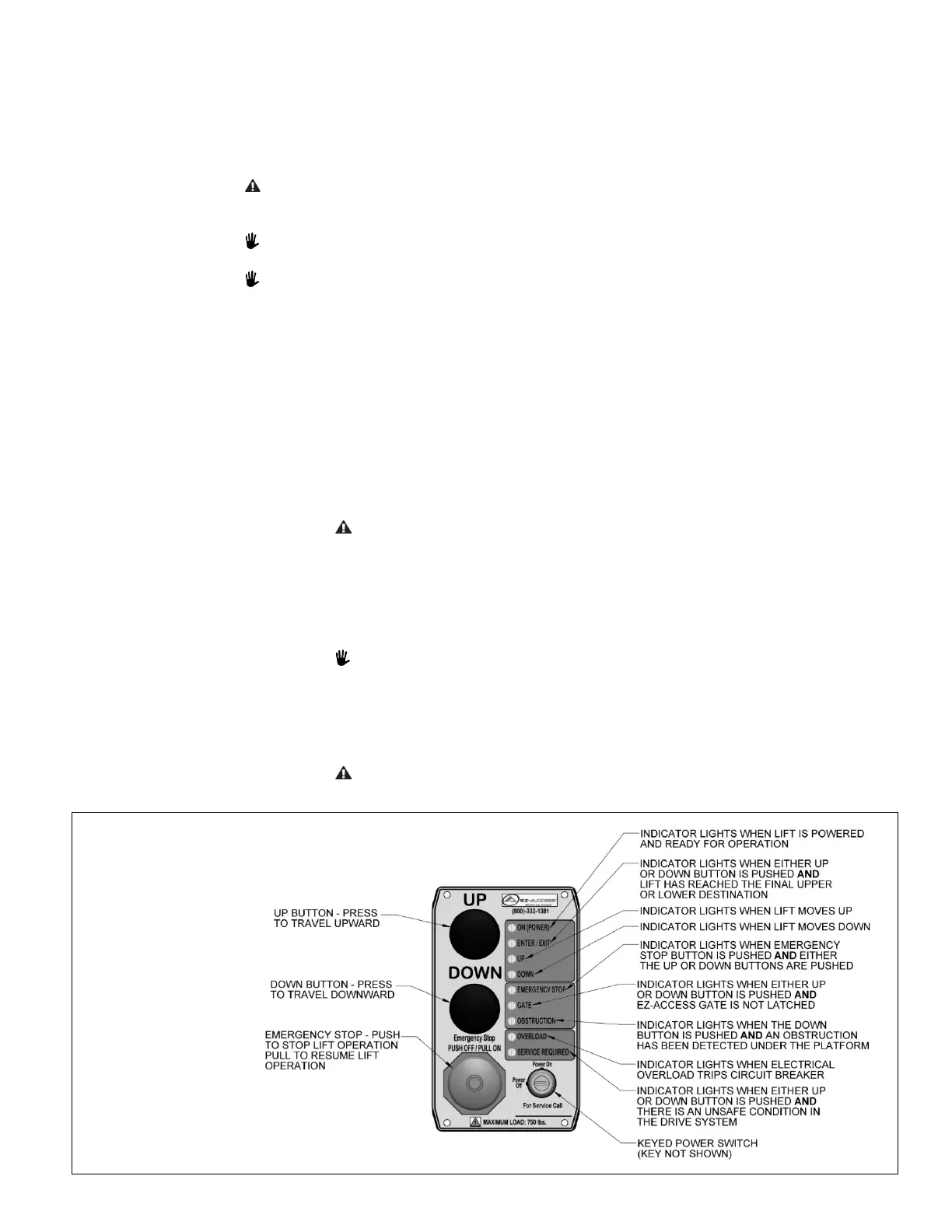
14.2. CONTROL PANEL
14.2.1. The control panel (FIG. 14.1) incorporates operational controls as well as function indicator
lights. Control functions and features are as follows:
14.2.1.1. When turned to the ‘Power On’ position, the keyed power switch permits VPL
operation. When turned to the ‘Power Off’ position, the VPL will not ascend or
descend.
14.2.1.2. The key is removable in both the ‘Power On’ and ‘Power Off’ positions. If AC power
is disconnected from the VPL, leaving the key in the ‘Power On’ position will
discharge fully charged, non-damaged, batteries over approximately 7 days. The
batteries will charge with the key switch in either the ‘Power On’ or ‘Power Off’
position, provided the unit is plugged into AC power.
Removing the key from the keyed power switch does not disconnect
battery charger power. The only way to disconnect battery charger power
is to unplug the VPL from the AC outlet.
14.2.1.3. The force needed to operate the ‘UP’ or ‘DOWN’ push buttons is minimal. The VPL
platform will travel upward by pressing and holding the ‘UP’ button. The VPL
platform will travel downward by pressing and holding the ‘DOWN’ button. The
VPL will stop moving if either button is not pressed continually.
Although some initial LED flicker may be observed, ‘UP’ or ‘DOWN’
indicator lights are not to illuminate unless either the ‘UP’ or ‘DOWN’
buttons are pressed.
14.2.1.4. Pressing the ‘Emergency Stop’ button will remove power ONLY to the motor
controls. This will stop VPL from moving up or down. The ‘Emergency Stop’ Button
must be pulled back out to reset for continued operation.
To disconnect power to the battery charger, the VPL must be unplugged
from the AC outlet.
FIG. 14.1
(CONTROL PANEL
AND INDICATOR
LIGHTS)
 Loading...