7
ENGLISH
ENGLISH
3. ELECTRICAL EQUIPMENT (standards system)
aa
aa
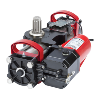
a Operators mod. 390
bb
bb
b Photocells
cc
cc
c Electronic equipment
dd
dd
d Key-operated push-button
ee
ee
e Radio receiver
ff
ff
f Flashlight
4. INSTALLATION OF AUTOMATION
4.1. PRELIMINARY CHECKS
To ensure safety and an efficient automation, make sure the
following requirements are met:
• The gate structure must be suitable for automation. In
particular, make sure it is sufficiently sturdy and rigid, and
that its dimensions are in line with those indicated in the
technical specifications.
• Make sure that the leaves move properly and uniformly,
without any irregular friction during their entire travel.
• Check if hinges are in good condition.
• Make sure the travel limit mechanical stops are present.
We advise you to carry out any metalwork jobs before installing
the automation.
4.2. INSTALLATION DIMENSIONS
Establish the installation position of the operator by consulting
Fig. 4-5-6.
Fig. 3
Notes:1) To lay electrical cables, use adequate rigid
and/or flexible tubes.
2) Always separate low voltage accessories from
those operating at 230V~. To avoid any interfer-
ence, always use separate sheaths.
D
max
= 240 mm
á°
A
D
BC
40/60
ABCá
100÷200 110÷130 350 90°
200÷300 110÷130 250 90°
Fig. 6
70
~200
Fig. 4
•
measurements in mm
•
measurements in mm
4.2.1. RECOMMENDED DIMENSIONS FOR INWARD
OPENING
4.2.2. RECOMMENDED DIMENSIONS FOR OUTWARD
OPENING
ABCá
50÷150 110÷130 610 90°
150÷250 110÷130 600 90°
250÷350 110÷130 580 90°
50÷150 250÷270 480 120°
150÷250 310÷330 400 120°
BC
D
A
á°
40/60
D
max
= 300 mm
Fig. 5
•
measurements in mm
59 mm
59 mm