6
FAAC Model S450H 24V Hydraulic Swing Gate Operator
Operator Specications
Model S450H 24V Hydraulic Swing Gate Operator
2
1
1
2
2
2
5
3
4
6
6
RX
RX
TX
TX
7
a
b
c
d
e
f
g
1. DESCRIPTION AND TECHNICAL
SPECIFICATIONS
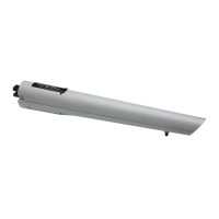
1.1 DIMENSIONS
a Front tting
b Cover
c Emergency release with key
d Plastic cover for rear bracket
e Rear bracket
f Encoder
g Spacer for opening mechanical stop
TECHNICAL
SPECIFICATIONS
CBAC
OPERATOR
SB
OPERATOR
Power Supply (VDC) 24 - 36
Power Consumption (W) 70 (nominal) - 288 (maximum)
Protection Class IP 55
Oil Type FAAC HP OIL
Operating Temperature -4°F to +113°F
Hydraulic Lock Installed Not installed
Max. Traction/Thrust Force (lbf) 1124
Max. Opening Angle See table 1
Max. Leaf Length (feet) 14 16
Linear Rod Speed adjustable up to 1"/sec
Effective Rod Stroke (inches) 12 1/4
Operator Weight (lbs) 15.6 15.2
2. PRESETS
S450H operators (2x2.5 mm² each motor)
(2x0.5 mm² each encoder bus)
RX Photocells (receiver)
(TRADITIONAL: 4 x 0.5 mm²; 2easy bus: 2 x 0.5 mm²)
TX Photocells (transmitter) (2 x 0.5 mm²)
Electronic control unit (power supply 3 x 1.5 mm²)
Key-operated push-button (e.g. T11) (3 x 0.5 mm²)
Flashing lamp 24 V dc (2 x 1 mm²)
Opening mechanical stops*
Electric lock and closing mechanical stop (2 x 1.5 mm)
* Not necessary when using opening mechanical stops inside the
operator (Fig.1 Ref. 7).
3. INSTALLING THE AUTOMATED
SYSTEM
Ensure that the following conditions have been met to ensure safety
and the efcient operation of the automated system:
• The gate structure must be suitable for automation. Verify that it is
sufciently strong and that its dimensions and weight correspond
to those stated in the technical specications.
• Verify the smooth and uniform movement of leaves, without irregu-
lar friction during the entire travel.
• Verify the good condition of hinges.
• Verify the presence of mechanical limit switches.
• Remove any locks and bolts.
• Carry out any metalwork operations before installing the
automated system.
Fig. 1
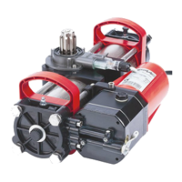
The FAAC S450H automated system for swing-leaf gates con-
sists of an electrical pump and an hydraulic piston transmitting
the leaf movement, assembled in a single block.
The model with hydraulic locking can automate leaves up to
6.5 feet long. It does not require the installation of electric
locks and guarantees that the leaf is mechanically locked
when the motor is not in operation. The model without hydrau-
lic locking always needs one or more electric locks to guaran-
tee the leaf mechanically locks. S450H automated systems
have been designed and built to automate swing-leaf
gates. Avoid any other use, whatsoever.
Fig. 3
43¾
29½
12¼
4¾
3⅜
3⅜
Dimensions in Inches
Fig. 2
 Loading...