9
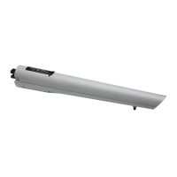
FAAC Model S450H 24V Hydraulic Swing Gate Operator
a
b
2. While referring to Table 1 (see white or grey boxes),
choose the xing hole on the rear bracket and install the
fork (Fig. 7 Ref. a) by assembling it with the special pin
supplied (Fig. 7 Ref. b).
3. Install the encoder on the rear bracket by correctly
engaging it on the pin, then x it with the screw and nut
supplied (Fig. 8 Ref. a, b and c).
4. Slightly press the protection cover on the rear bracket
until it locks in position (Fig. 9).
a
b
xx°(3)
xx°(2)
xx°(1)
Fig. 7
3.2 INSTALLING THE OPERATOR
1. Check the perfect level then weld the rear tting to the pil-
lar or x it by means of suitable screws, dowels / thread-
ed inserts. Observe the dimensions stated in Tab.1 (never
cut the rear tting; moreover it must be installed with the
word "UP" facing up as shown in Figure 6 Ref. a).
a
b
c
Fig. 8
b
a
Fig. 10
Fig. 11
6. Screw one-half of the thread of the front articulated joint
on the operator rod and tighten the nut (Fig. 11 Ref. a).
7. Unlock the operator according to Section 4.
8. If no external mechanical stop point at closure is present,
you may use the stop point inside the operator (extend
the rod completely up to its internal stop point).
9. If an external mechanical stop point at closure is present,
extend the rod completely and then insert it 0.25 in.
10. Close the gate leaf and install the front tting on the rod
as shown in Fig. 11 Ref. b.
HOLE FOR
ENCODER
CABLE
ROUTING
a
INSTALL THE BRACKET
WITH THE WORD “UP”
FACING UP
Fig. 6
Fig. 9
HOLE FOR
ENCODER
CABLE
ROUTING
5. Assemble the operator and the rear bracket by means of
the pin and nut supplied (Fig. 10 Ref. a - b).
 Loading...