7
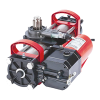
FAAC Model S450H 24V Hydraulic Swing Gate Operator
TAB. 1
B
2.95-3.3
3.35-3.7 3.75-4.0
4.1-4.45 4.5-4.85 4.9-5.25 5.3-5.65 5.7-6.0 6.1-6.45 6.5-6.85
D
0.75-0.95
110° (3) 110° (3) 115° (3) 108° (3) 100° (3) 100° (3)
1.0-1.3
108° (3) 110° (3) 110° (3) 103° (3) 100° (3) 94° (3)
1.35-1.7
100° (3) 107° (3) 108° (3) 104° (3) 111° (2) 104° (2) 100° (2)
1.75-2.1
100° (3) 105° (3) 106° (3) 100° (3) 106° (2) 100° (2) 96° (2)
2.15-2.5
97° (3) 100° (3) 105° (3) 99° (3) 107° (2) 100° (2) 96° (2) 92° (2)
2.6-2.9
93° (3) 97° (3) 100° (3) 100° (3) 110° (2) 101° (2) 96° (2) 102° (1) 98° (1)
2.95-3.3
90° (3) 95° (3) 100° (3) 105° (2) 102° (2) 111° (1) 105° (1) 98° (1) 94° (1)
3.35-3.7
90° (3) 90° (3) 95° (3) 100° (2) 104° (2) 96° (2) 104° (1) 100° (1) 94° (1) 90° (1)
3.75-4.0
90° (3) 90° (3) 95° (3) 100° (2) 96° (2) 106° (1) 98° (1) 96° (1) 90° (1)
4.1-4.45
90° (3) 90° (3) 95° (2) 97° (2) 103° (1) 99° (1) 94° (1) 92° (1)
4.5-4.85
90° (3) 90° (2) 95° (2) 98° (1) 100° (1) 94° (1)
4.9-5.25
90° (2) 90° (2) 95° (1) 98° (1) 94° (1)
5.3-5.65
90° (2) 90° (2) 95° (1) 94° (1)
5.7-6.0
90° (1) 90° (1) 94° (1)
6.1-6.45
90° (1) 90° (1)
6.5-6.75
90° (1)
3⅜
41¾
2
3
4
Z
a° (3)
a° (2)
D
a° (1)
(3)
(2)
(1)
TAB.1
B
XXX XXXX
D
XXX 120° (3) 120° (3)
XXX 110° (2) 110° (2)
XXX 115° (1) 110° (1)
a
B
ATTENTION: do not cut the rear bracket for any reason.
Refer to Figures 4 and 5 and Table 1 to determine the installation position of the operator.
INSTALLATION DIMENSION "B"
(SEE FIGURES 4 and 5)
INSTALLATION
DIMENSION
"D"
(SEE FIGURE 5)
- INTERSECT THE DIMENSIONS "D" AND "B" TO OBTAIN THE MAXIMUM VALUE OF OPENING ANGLES.
- ATTENTION: USE MECHANICAL LIMIT SWITCHES IN ORDER NOT TO EXCEED THE MAXIMUM OPENING ANGLES STATED IN TABLE 1 AND GUARANTEE
THE CORRECT OPERATION OF THE AUTOMATED SYSTEM.
HOLE TO BE USED
ON THE REAR
BRACKET
HOLE TO BE USED ON THE REAR BRACKET
Dimensions in Inches
Fig. 4
Fig. 5
Dimensions in Inches
3.1 INSTALLATION DIMENSIONS
3.1.1 APPLICATION WITH BRACKET FASTENED TO THE COLUMN
- - If the gate structure does not allow the stable xing of the front tting, create a rm bearing surface in the leaf structure.
- It is advisable to grease all xing pins - Opening and closing stops must always be installed - Pay special attention not to
damage the operator rod.
 Loading...