PageChapter: 6 Section:
PROGRAMMING 17
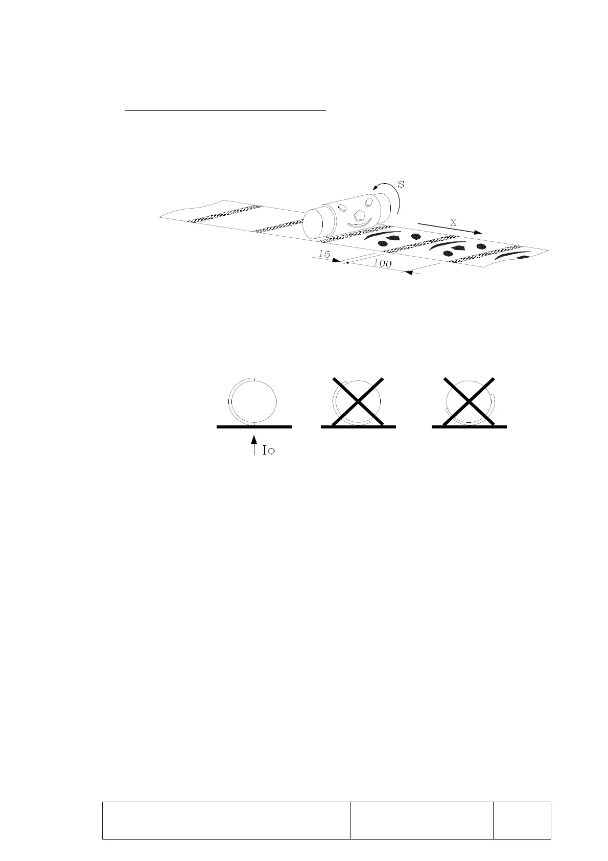
Example of synchronized stamp printing
A roller with half of its surface covered with a stamp is being used.
This figure has to be stamped on continuous paper.
The resulting image takes up 100 mm and a space of 15 mm between each two images
is to be left.
The feedback for the paper feeder will be taken to connector A1 and will correspond
to axis X.
The roller covered with the stamp should have an encoder. Said feedback should be
taken to connector A2.
Make the Io signal for the feedback from the roller covered with the stamp coincide with
the start of the printing process.
To carry out printing as shown in the figure the following should be programmed:
N0 S1000 M3 ............ ; Turning direction and speed of the roller covered
with the stamp
N1 G0.91 X15 ........... ; Fast feed across the space to be left between 2
images.
N2 G33 X100 K200 . ; Printing of an image
The value in X indicates the distance to be moved, 100 mm
The value of K indicates the positioning of axis X per spindle turn. As in this
case 100mm has to be moved for each half turn of the roller, K200 should be
programmed.
N3 G25 N1 ............... ; Repetition of the process.
Operation:
The paper fast feeds across the space that has to be left between 2 images, 15 mm.
Waiting stage until the Io signal for the feedback from the roller covered with the
stamp is received.
Printing of the image. The positioning of axis X is synchronized with the roller
turn.
After covering the 100 mm the paper again fast feeds and the cycle is repeated.
PATH CONTROL