AUX MODE2
Section:Chapter: 2
Page
2.1 SYSTEM INPUT/OUTPUT TEST
With this option, it is possible to analyze the status of the logic inputs and outputs of
the CNC as well as activating and deactivating each logic output.
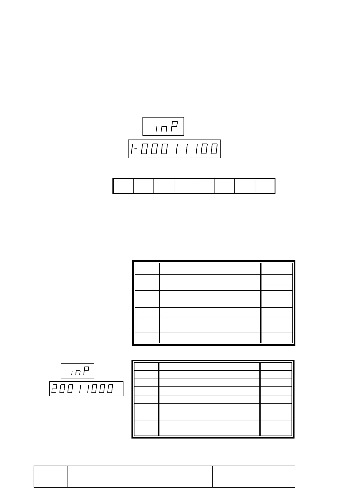
To do this, press the following keystroke sequence: [AUX MODE] [0]
The CNC displays the status of the first set of inputs (INP)
The lower display shows the status of 8 logic inputs, one digit per input.
The CNC, shows at all times and dynamically, the status of the inputs. To check a
particular one, actuate the corresponding external push button or switch and observe
the status change on the corresponding digit on the CNC display.
A "1" on the display digit indicates that its corresponding input is receiving 24 Vdc.
and a "0" means that it is not receiving 24 Vdc.
The inputs appearing at the lower window are:
To display the next set of inputs, press [A+]
The data shown at digits 6, 5, 4, 3, 2 and 1 is internal CNC information.
Bottom Display
Digit
8
Digit
7
Digit
6
Digit
5
Digit
4
Digit
3
Digit
2
Digit
1
SYSTEM I/O TEST
Digit Corresponding Input Pin
8 Manual Input (DRO mode) 19 (I/O1)
7 Conditional Stop (M01) / Block Skip 18 (I/O1)
6 Cycle Start 17 (I/O1)
5 / Cycle Stop 16 (I/O1)
4 / Feed Hold 15 (I/O1)
3 / Emergency Stop 14 (I/O1)
2 X axis Home switch 13 (I/O1)
1 Reset 12 (I/O1)
Digit Corresponding Input Pin
8 External feedrate override 2 11 (I/O1)
7 External feedrate override 1 10 (I/O1)
6 X axis feedback error
5 Y axis feedback error
4 X axis sine-wave feedback alarm
3 Y axis sine-wave feedback alarm
2 Over-temperature
1 Not being used at this time