AUX MODE
3
Chapter: 2 Section: Page
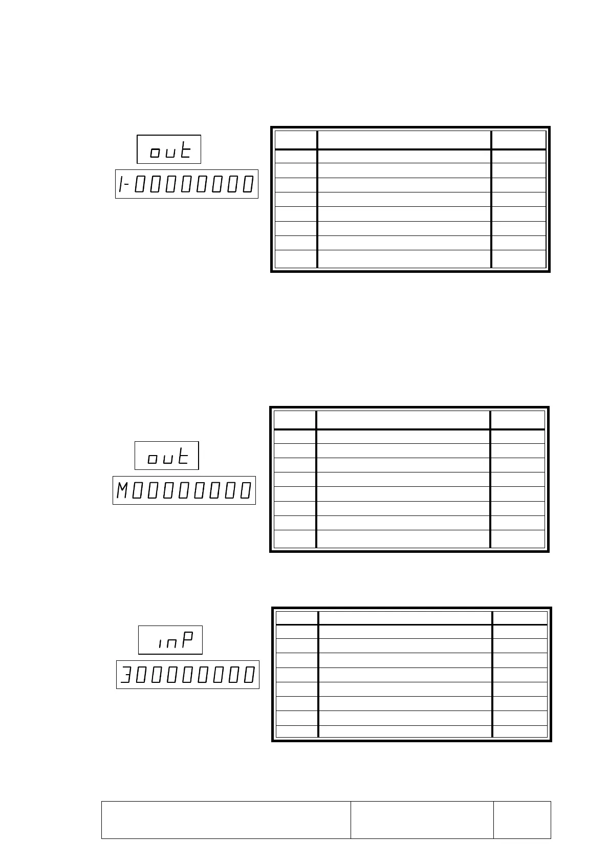
To display the first set of outputs, press [A+]
To check a particular output, select it by using the up and down arrow keys.
Once the desired output has been selected, it could be turned on (1) or off (0) by
pressing [1] or [0].
Several outputs may be active at the same time and they will all output 24 Vdc. at their
corresponding connector pin.
To display the next set of outputs, press [A+]
If [A+] is pressed again, the CNC will display the third set of inputs.
SYSTEM I/O TEST
Digit Corresponding Input Pin
8 E5 17 (I/O2)
7 E4 25 (!/O2)
6 E3 22 (I/O 2)
5 E2 23 (I/O 2)
4 E1 21 (I/O 2)
3 Mult. factor, handwheel or JOG type posit. 24 (I/O 2)
2 Mult. factor, handwheel or JOG type posit. 15 (I/O 2)
1 Y axis home switch 18 (I/O 2)
Digit Corresponding Output Pin
8 X axis In Position 9 (I/O1)
7 X axis Direction (Open Loop) 8 (I/O1)
6 X axis Slow (Open Loop) 7 (I/O1)
5 X axis Fast (Open Loop) 6 (I/O1)
4 / Emergency 5 (I/O1)
3 M Strobe 4 (I/O1)
2 X axis Brake 3 (I/O1)
1 Jog mode selected 2 (I/O1)
Digit Corresponding Output Pin
8 MST80 20 (I/O1)
7 MST40 21 (I/O1)
6 MST20 22 (I/O1)
5 MST10 23 (I/O1)
4 MST8 24 (I/O1)
3 MST4 25 (I/O1)
2 MST2 26 (I/O1)
1 MST1 27 (I/O1)