Section:
Page
PROGRAMMING34
Chapter: 6
PARAMETRIC
PROGRAMMING
N008 P9 E4 P9 takes the value corresponding to input E4. Pin 25 of connector
I/O2. A value of "0" when E4 = 0V and "1" when E4 =24V.
N009 P10 E5 P10 takes the value corresponding to input E5. Pin 17 of connector
I/O2. A value of "0" when E5 = 0V and "1" when E5 =24V.
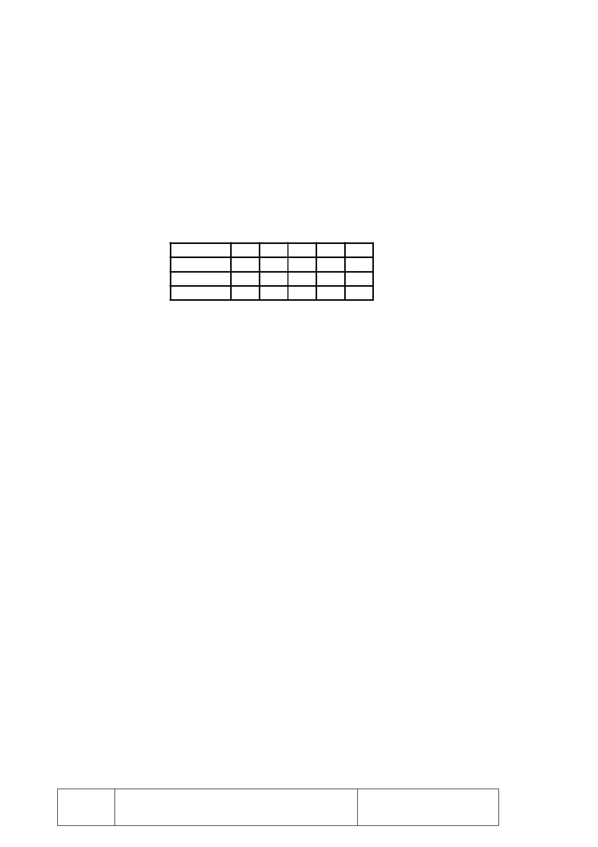
N010 P11 E0 P11 takes the value corresponding to the status of inputs E1, E2,
E3, E4 and E5.
For example P11 = 2
4
+ 2
2
+ 2
1
= 16 + 4 + 2 = 22
6.9.2 OPERATIONS
The operations that may be performed between arithmetic parameters or between
arithmetic parameters and numeric constants (K) are:
F1 Addition
F2 Subtraction
F3 Multiplication
F4 Division
F5 Square root
F6 Square root of the sum of squares
F7 Sine
F8 Cosine
F9 Tangent
F10 Arc tangent
F11 Comparison
F12 Integer
F13 Integer plus one
F14 Integer minus one
F15 Absolute
F16 Complement
F1 Addition
N101 P10 P11 F1 P12 Means P10 = P11 + P12
N102 P10 P11 F1 K2 Means P10 = P11 + 2
N103 P10 K8 F1 K2 Means P10 = 8 + 2 = 10
N104 P10 P10 F1 K2 Means P10 = P10 + 2
F2 Subtraction
N101 P10 P11 F2 P12 Means P10 = P11 - P12
N102 P10 P11 F2 K2 Means P10 = P11 - 2
N103 P10 K8 F2 K2 Means P10 = 8 - 2 = 6
N104 P10 P10 F2 K2 Means P10 = P10 - 2
Input E5 E4 E3 E2 E1
Voltage 24V 0V 24V 24V 0V
Logic State 1 0 1 1 0
Value 2
4
2
3
2
2
2
1
2
0