Drive modules
DRIVE MODULES
Modular drives
3.
141
DDS
HARDWARE
Ref.1310
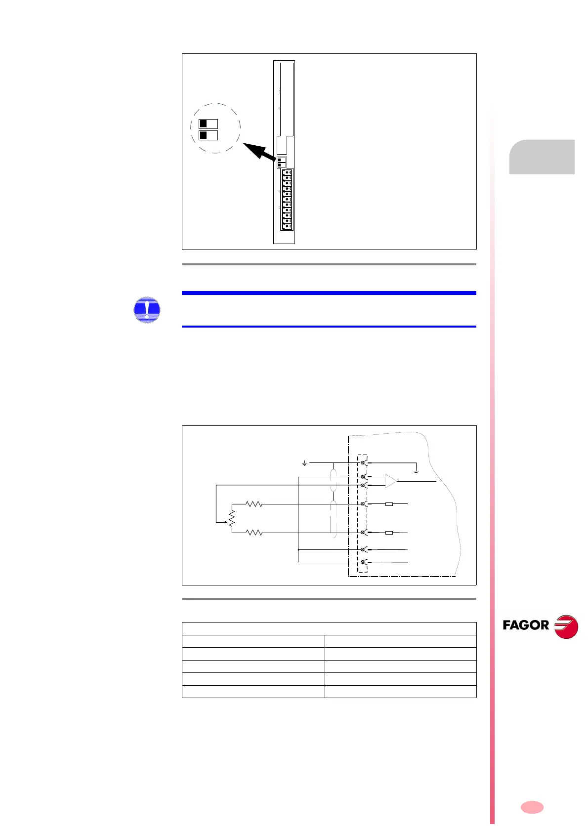
Dip-Switches (DS1, DS2)
Adjustment outputs
With these outputs and a potentiometer, the user can obtain a variable an-
alog voltage for adjusting the servo system during setup.
The voltage, with no load, at these pins is ±15 V DC.
The electrical circuit necessary to obtain a reference voltage and the rec-
ommended resistance values to obtain an approximate range of ±10 V
DC for the Vref are described next:
F. H3/78
Factory settings of the dip-switches (DS1, DS2).
A1
1
1
X7-ANALOG I/Os X6-DIGITAL I/Os
P2P1
DS1
DS2
MANDATORY. The status of the dip-switches (DS1, DS2) must not be
changed by the operator.
F. H3/79
Adjustment outputs.
Range ±10 V
Rext. R’
1 k
0
5 k 820
10 k 1.8 k
20 k 3.3 k
5
4
1
7
+15 V DC
X7
GND
Vref
R'
R'
Rext
DRIVE
6
-15 V DC
8
10
 Loading...
