10.
Shielded by pairs of cables and overall shield.
The shields of twister pairs must be connected to each other and only at the
drive end joined to the common pin of the chassis (pin 26). The overall screen
must be connected to the connector housing at the drive end and to the metallic
housing and to pin 9 of the connector at the motor end.
The housing of the 26-pin connector must be conductive (metallic).
X2
IN
OUT
X2
1
10
(Phoenix, 5.08mm)
IN
OUT
NODE
SELECT
4
0
8
7
6
3
5
4
8
2
1
SPEED ENABLE
DRIVE ENABLE
DR. O.K.
9
10
PROG. OUT
ERROR RESET
+24 V DC
0 V
Ri
Re
L+
X1
3
(Phoenix,
7.62 mm)
1
2
3
1
X1
1 A
(T) Fuses
May be connected
in any order.
2 x 400-460 V AC
Internal
use.
110 mA máx
OP5
5
4
3
2
1
10
9
8
7
6
11
- 15 V
+15 V
5
4
3
2
1
9
8
7
6
+15 V DC
13
12
11
10
A1 Board
P2
P1
Programmable
Inputs (24 V DC)
Programmable
Outputs
(24 V-1A)
IN-1
IN-2
IN-3
IN-4
OUT-1
OUT-2
OUT-3
OUT-4
Analog Output 1
(-)
(+)
IV2
IV1
OP2
OP1
(-)
(+)
Analog Output 2
(-)
(+)
(-)
(+)
OP4
OP3
OP13
OP10
IP10
IP13
OP12
OP11
IP11
IP12
OV2
OV1
1
2
3
4
A
/A
B
/B
5
6
7
8
Io
/Io
11
0 V
(HD, Sub-D, F15)
Reserv.
Reserv.
1
5
11
15
(HD,
Sub-D,
M15)
2
3
RxD
TxD
Serial Line
Interface
Board
(Sub-D, F9)
1
5
6
9
(Sub-D, F9)
X5
1
5
6
9
(Sub-D, M9)
X5
RxD
TxD
2
3
1
2
3
4
5
6
7
8
11
(Sub-D, M15)
(Sub-D, M9)
X4
9
1
26
19
(HD,
Sub-D,
F26)
Green
Yellow
Blue
Purple
Grey
Pink
Brown
White
Black
1
13
1
11
(Phoenix, 3.5 mm)
(Phoenix, 3.5 mm)
Analog Input 2
Analog Input 1
POWER MAINS
May be connected
in any order.
400/460 V AC
L-
Internal
Ballast
AUXILIARY POWER SUPPLY
M
3
MPC- 4x...(mm²)
MPC- 4x...(mm²)+2x1
U
V
W
6
5
3
2
4
1
+24 V DC
X1
(Phoenix,7.6 mm,M3)
U
V
W
Cable without connectors
MC-20/6 socket
MC-20/6 base
5
4
6
1
2
3
PTC
EOC - 12
(HD, Sub-D, M26)
X4
Blue
Black
Green
Brown
Grey
Purple
White
Red
20
19
11
2
10
1
21
22
10
2
6
5
1
8
3
4
26
25
12
REFCOS
SIN
REFSIN
+485
-485
GND
+8 VDC
COS
7
23
X2
Yellow
Black
E3 SINCOS SINUSOIDAL
ENCODER
CHASSIS
SIN
REFSIN
+485
GND
+8 VDC
KTY84 -
+t°
E0C 12
1
2
3
4
11
1012
7
8
6
5
9
Front View
KTY-84
KTY84 +
KTY84 +
KTY84 -
Cable 3x2x0.14+4x0.14+2x0.5
COS
REFCOS
- 485
Cable 4x2x 0.14+2x0.5
SL1
X6-DIGITAL I/Os
X7-ANALOG I/Os
X6-DIGITAL I/Os
X7-ANALOG I/Os
P2
P1
AS1
X7
(Phoenix,
5.08 mm)
AS2
Relay
N.C.
or
with brake
without brake
5
1
11
15
(HD,Sub-D,F15)
9
- 15 V DC
Digital Axis Compact Drive
ACD 1.15 - SI ...
SEC-HD 1/3/5/10/15/20/25/30/35
Ready made cable to 8055/55i CNC,
Length in meters; including connectors
R
S
T
Encoder simulator
option
X3
EEC-SP 5/10/15/20/25/30/35/40/45/50
Length in meters; including connectors
Ready made cable
X3
Holding brake (option)
24 V Released
0 V Holding
Axis Motor
FKM...E3...
PC-Computer
MPC- 4x...
L1
L2
CNC 8055/55i
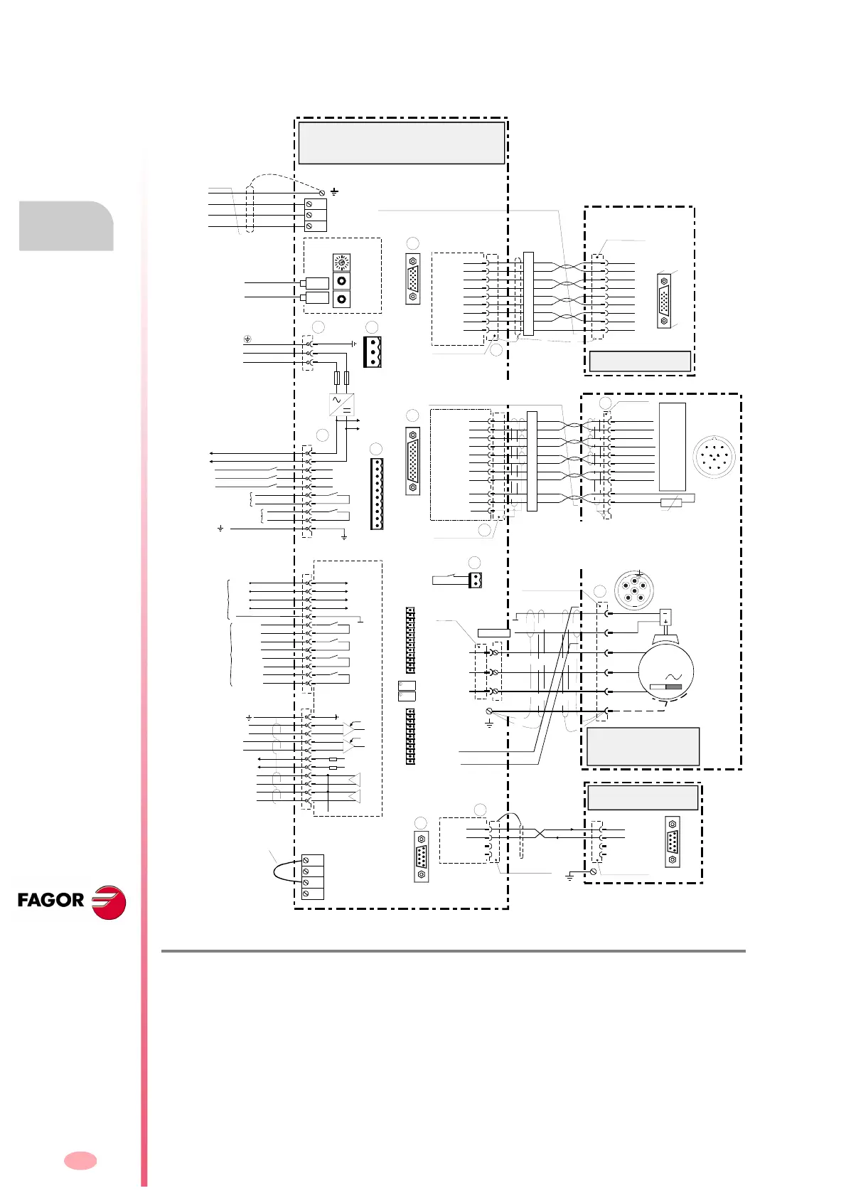
Connection diagram of an ACD
compact drive with an FKM
synchronous axis motor that
has encoder feedback.
 Loading...
