N
EW
F
EATURES
(S
OFT
M: 7.
XX
)
Page 23 of 50
CNC 8055 / CNC 8055i
Improvement in the
tool measuring
cycle PROBE1
If the maximum allowed is exceeded, it issues a "tool rejected"
message and acts as follows:
If the measuring difference does not exceed the maximum allowed
or tool life monitoring is not available:
•
It updates global arithmetic parameter P299 and the length wear
value of the tool offset selected in the tool offset table.
If the dimension of each cutting edge was requested, "N" parameter,
the measured values are assigned to global arithmetic parameters
P271 and on.
31.2 Measure or calibrate the radius of a tool.
It may be carried out either with the spindle stopped or turning the in
the programmed direction (opposite to the cutting direction)
Calibration format:
(PROBE 1, B,
I2
, F, J0, K, E, S, N, X, U, Y, V, Z, W)
Format for wear measurement:
(PROBE 1, B,
I2
, F, J1, K, E, S, M, C, N, X, U, Y, V, Z, W)
Parameters J, E, S, M, C, N are optional. If not programmed, the
following values are assumed:
C0 It interrupts the execution for the user to select another tool.
C1
The cycle replaces the tool with another one of the same
family.
It sets the "rejected tool " indicator (status = R)
It activates the general logic output PRTREJEC (M5564)
P299 = measured length - theoretical length (L)
L = theoretical length (it maintains the previous value).
K = measured length - theoretical length (L) [New wear value]
B Safety distance, with positive value greater than "0".
I2 Measure or calibrate the radius of a tool.
F Probing feedrate, in mm/min. or in inches/min.
J J0 = Calibration; J1 = Measurement
K
Probe side used.
K0 (X+ side), K1 (X- side), K2 (Y+ side), K3 (Y- side).
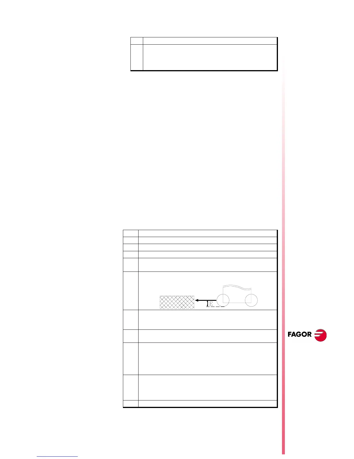
E
Distance referred to the theoretical tool tip being probed. It is
very useful with cutters whose bottom is not horizontal.
S
Tool turning speed and direction. Select the opposite of the
cutting direction (positive sign if M3 and negative if M4)
With S0, calibration with spindle stopped.
M
Maximum radius wear permitted (with J1 and when using tool
life monitoring).
C
Behavior when exceeding the maximum wear allowed (M other
than 0).
C0 = Interrupts the execution for the user to select another tool.
C1 = The cycle replaces the tool with another one of the same
family.
N
Number of cutting edges to be measured. If N0, one
measurement.
To measure each cutting edge when the spindle has feedback
and s.m.p. M19TYPE (P43) =1.
X...W Optional
 Loading...


