Page 44 of 50
CNC 8055 / CNC 8055i
Detected errors
N
EW
F
EATURES
(S
OFT
M: 7.1
X
)
50
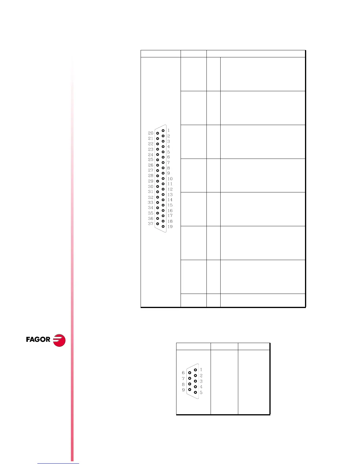
Connector X2. I/O module (8055 model).
The installation manual indicates that input I65 is assigned to pin 1.
Actually, input I65 is assigned to pin 2. The right pin values are:
Connector X3. RS232 serial line (8055 model)
Connector X1. RS232 serial line (8055i model)
From this version on, pin 9 no longer supplies 5V.
Pin Signal and Function
1
2
3
4
5
-----
I65
I67
I69
I71
6
7
8
9
10
I73
I75
I77
I79
I81
11
12
13
14
15
I83
I85
I87
I89
I91
16
17
18
19
20
I93
I95
0V
0V
-----
External power supply
External power supply
21
22
23
24
25
I66
I68
I70
I72
I74
26
27
28
29
30
I76
I78
I80
I82
I84
31
32
33
34
35
I86
I88
I90
I92
I94
36
37
I96
Chassis - Shield
Pin Signal
1 DCD
2RxD
3TxD
4DTR
5 GND ISO
6 -----
7RTS
8CTS
9 -----
 Loading...


