Hardware configuration
CNC 8065
8.
(REF: 1404)
·91·
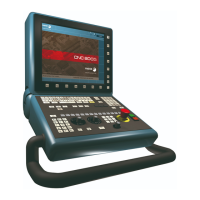
OP-PANEL MODULE. OPERATOR PANEL WITH OR WITHOUT
SPINDLE SPEED OVERRIDE SELECTOR.
Power supply.
3-pin male Phoenix combicom contact (7.62 mm pitch).
Connector to power the keyboard with universal 24 V DC.
CAN bus. ·CAN· connector.
5-pin male Phoenix minicombicon contact (3.5 mm pitch).
For further information on how to configure the connection of the elements to the CAN bus,
refer to chapter "10 Bus CAN (CANfagor/CANopen protocols)." of this manual.
CAN bus. ·ADDRESS· selector. Address (node) of the element within the bus.
The CNC must always occupy position "0" and the rest of the elements of the bus will occupy
consecutive positions starting with 1. In order for any change at the "Address" switch to be
assumed, the CNC must be restarted and the corresponding drive must be reset, however,
we recommend to change the address while the modules and the CNC are off.
The "Address" switch also sets the priority of the group within the bus; the lower the number
the higher the priority. We recommend the keyboard and jog panel to be the last node of the
bus.
CAN bus. ·ADD MSB· selector Address (node) of the element within the bus.
With the ·4· switch (ADD MSB), the positions or elements integrated in the CAN bus may
be expanded up to 32. Positions 0-15 are selected with ADD MSB=0 and positions 16-31
with ADD MSB=1.
CAN bus. Bus type selector: CANfagor / CANopen.
Switch ·1· (CAN F/O) selects the type of CAN bus to by used, i.e. CANfagor or CANOpen.
Each one of the elements integrated into the CAN bus is identified
by the 16-position rotary switch (0-15) "Address" (also referred to
as "Node_Select"). With the ADD MSB" switch, the positions or
elements integrated in the CAN bus may be expanded up to 32.
Signal. Function.
Ground. Ground.
0 V Power supply.
+24 V Power supply.
Pin. Signal. Function.
1 ISO GND Ground / 0 V.
2 CAN L (LOW) bus signal.
3 SHIELD CAN shield.
4 CAN H (HIGH) bus signal.
5 SHIELD CAN shield.
12345
ISO GND
CAN L
SHIELD
CAN H
SHIELD
123
4
ON
CAN F/O
CO BR
ADD MSB
DS ·4· Address (node) of the element.
off Positions 0-15 within the bus.
on Positions 16-31 within the bus.
123
4
ON
CAN F/O
CO BR
ADD MSB
DS ·1· Type of CAN bus.
off The CANfagor bus has been selected.
on The CANopen bus has been selected.

 Loading...