·92·
Hardware configuration
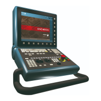
CNC 8065
8.
(REF: 1404)
OP-PANEL MODULE. OPERATOR PANEL WITH OR WITHOUT
SPINDLE SPEED OVERRIDE SELECTOR.
CAN bus. Selecting the baudrate for the CANopen bus.
When using the CANopen protocol, the transmission speed at the bus is defined in each node
and they all must run at the same speed. The speed is selected with switches ·2· and ·3· (CO
BR).
The transmission speed depends on the total length of the bus. Using the following illustrative
values; assigning other values may cause communication errors due to signal distortion.
In order for any change of speed to be assumed, the corresponding module must be reset;
however, we recommend to change the speed while the modules and the CNC are off.
CAN bus. ·ST· selector.
The switch position of the terminating elements must be "1" and that of the rest of the
elements "0".
·HANDWHEEL· connector. Handwheel connection.
10-pin male Phoenix minicombicon contact (3.5 mm pitch).
Line terminating resistor. The ·LT· switch identifies which are the
elements that occupy the ends of the CAN bus; i.e. the first and last
physical element in the connection.
123
4
ON
CAN F/O
CO BR
ADD MSB
DS ·2· DS·3· Speed Length of the CAN bus.
on on 1000 kHz Up to 20 meters.
off on 800 kHz From 20 to 40 meters.
on off 500 kHz From 40 to 100 meters.
off off 250 kHz From 100 to 500 meters.
Pin Signal Function
1 +5 V Power supply.
2- - -
3- - -
4 MPG3-B B signal of the third handwheel.
5 MPG3-A A signal of the third handwheel.
6 MPG2-B B signal of the second handwheel.
7 MPG2-A A signal of the second handwheel.
8 MPG1-B B signal of the first handwheel.
9 MPG1-A A signal of the first handwheel.
10 GND Power supply.
789 34561210
MPG2-B
MPG2-A
MPG1-B
MPG1-A
GND
MPG3-B
MPG3-A
5 V DC

 Loading...