Auxiliary modules
AUXILIARY MODULES
Auxiliary power supply. APS-24
4.
Ref.1912
· 193 ·
DDS
HARDWARE
Block diagram
NOTE. See chapter 13. COMPATIBILITY for the models of the
compatible APS-24 auxiliary power supplies with the XPS|RPS power
supplies in case it is installed.
INFORMATION. In case of micro-surges or total mains power outage, this
module guarantees the stability of the 24 V DC to feed the control circuits of
the drives connected to the bus and maintain it for as long as the emergency
stop of the motors lasts, thus stopping the axes in a controlled manner.
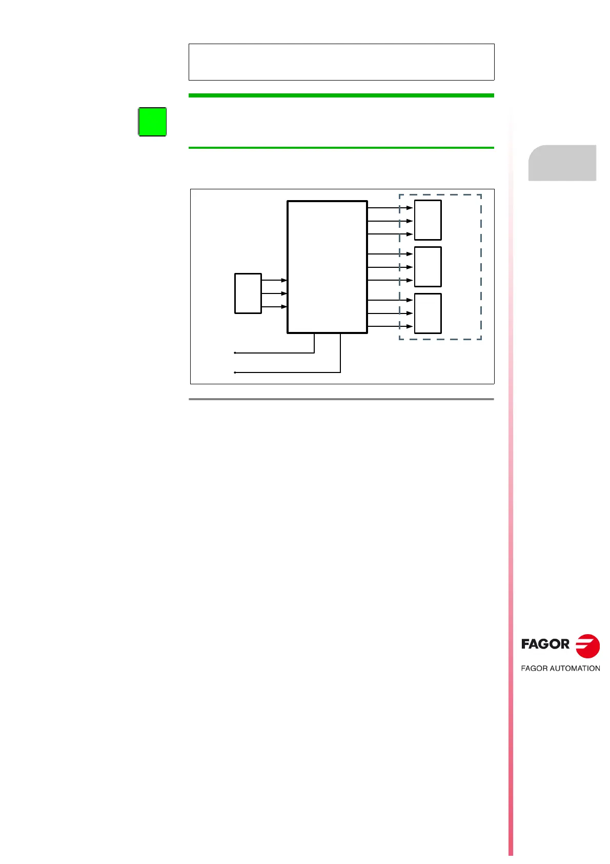
F. H4/9
Auxiliary power supply, APS-24. Block diagram.
X1
AUXILIARY
POWER
SUPPLY
APS-24
L1
L2
CHASSIS
L+
L-
X2
+24VDC
0VDC
CHASSIS
X3
+24VDC
0VDC
CHASSIS
X4
+24VDC
0VDC
CHASSIS
Imax total = 10 A
Pmax total = 240 W