CQR-42/56 Fagor Compact Drives and Motors Quick Reference. Ref.1910
CONNECTORS AT SLOTS SL1 AND SL2
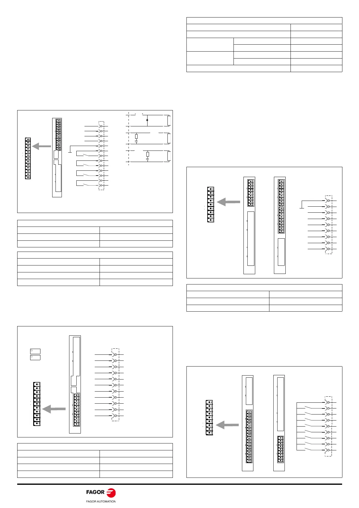
Card A1
The A1 Card must always be in slot SL1.
X6-DIGITAL I/Os, digital inputs and outputs
If offers 4 digital inputs and 4 digital outputs, all of them fully
programmable.
The digital inputs are optocoupled and referred to a common point
(pin 5). The digital outputs are contact type and also optocoupled.
Each input and output is associated with a parameter. The user may
assign to these parameters, internal Boolean type variables that may
be used to show the system status via electrical contacts.
X7-ANALOG I/Os, analog inputs and outputs
It offers 2 inputs and 2 outputs, all of them fully programmable.
Each input and output is associated with a parameter.
Cards 8DI-16DO and 16DI-8DO
These cards may be located in slot SL1 and/or SL2.
8DI-16DO offers to the user 8 digital inputs and 16 outputs.
16DI-8DO offers to the user 16 digital inputs and 8 outputs.
X8-DIG.INs, X11-DIG.INs, X12-DIG.INs, digital inputs
They offer 8 fully programmable digital inputs.
The digital inputs are optocoupled and referred to a common point
(pin 1) and they admit digital signals at 24 V DC.
Each input is associated with a PLC resource.
X9-DIG.OUTs, X10-DIG.OUTs, X12-DIG.OUTs. digital outputs
They offer 8 fully programmable digital outputs.
These outputs are optocoupled and of the contact type referred to a
common point (pin 1).
Each output is associated with a PLC resource.
Digital inputs characteristics
Nominal voltage (maximum) 24 V DC (36 V DC)
Turn ON/OFF input voltage 18 V DC (5 V DC)
Typical consumption (maximum) 5 mA (7 mA)
Digital outputs characteristics
Maximum voltage 250 V
Maximum load current (peak) 150 mA (500 mA)
Maximum internal resistance 24
Galvanic isolation voltage 3750 V (1 min)
Analog outputs characteristics
Resolution 4.88 mV
Voltage range ± 10 V DC
Maximum current ± 15 mA
Impedance (respect to GND) 112
IN 1
PIN
Phoenix,
3.5 mm
X6 - DIG ITA L I/ Os
A1
1
1
X7 -A N A LOG I/O s X6 -DIGITA L I/ Os
P2P1
A1 Board
1
13
IN 2
IN 3
IN 4
REF-IN
OUT 1
OUT 2
OUT 3
OUT 4
13
12
11
10
9
8
7
6
5
4
3
2
1
The schematics show the different ways to connect the digital
outputs to protect them against the effects of inductive loads.
DC
AC/DC
R ~1 Ohm
1N4000
Vbr =2 .4 V DC
IF=Lo ad
(1 Ohm)
C
0.1-1mF 250V
LOA D LOA D
AC/DC
R ~1 Ohm
C
0.1-1mF 250V
LOA D
X7 - A NA LOG I/ Os
A1
1
1
X7 - A N A LOG I/ Os
X6 -DIG ITA L I/ Os
P2P1
P2
P1
OUT2 -
OUT2 +
OUT1 -
OUT1 +
A1 Board
Phoenix,
3.5 mm
1
11
- 1 5 V DC
+ 1 5 V D C
CHAS S IS
ANALOG INPUT 2 -
ANALOG INPUT 2 +
ANALOG INPUT 1 -
ANALOG INPUT 1 +
PIN
1
2
3
4
5
6
7
8
9
10
11
Analog inputs characteristics
Resolution 1.22 mV
Input voltage range ± 10 V DC
Input overvoltage
Continuous mode
80 V DC
Transients
250 V DC
Input impedance
With respect to GND
40 k
Between both inputs
80 k
Voltage in common mode 20 V DC
Digital inputs characteristics configured at 24 V DC
Nominal voltage (maximum) 24 V DC (40 V DC)
ON/OFF voltage 12 V DC (6 V DC)
Typical consumption (maximum) 5 mA (7 mA)
X8 - D IG . INs
X11-DIG. INs
X12-DIG. INs
X8 -D IG. INsX9 - DIG . OU TsX1 0 -DIG. OUTs
8DI-16D0
X1 1 - D IG . INsX12-DIG. INsX13-DIG. OUTs
8 DI-1 6 DO Board 1 6 DI-8 DO Board
Phoenix,
3.5 mm
1
9
1
1
1
1 6 DI-8 D0
1
1
1
1
PIN
2
3
4
5
6
7
8
9
X9 - DIG. OUTs
X1 0 - DIG. OUTs
X1 3 - DIG. OUTs
X8 -D IG . IN sX9 -D IG . O U TsX1 0 -DIG. OUTs
X1 1 -D IG. IN sX1 2 - D IG . IN sX1 3 - D IG . OUTs
8 DI-1 6 DO Board 1 6 DI-8 DO Board
Phoenix,
3.5 mm
1
9
1
8DI-16D0
1
1
1
1 6 DI-8 D0
1
1
1
PIN
2
3
4
5
6
7
8
9