AC Brushless Servo Drive System Manual Ver: 0002
ACa - 25 / 32
Preliminary
8
10
9
VELOCITY
CURRENT
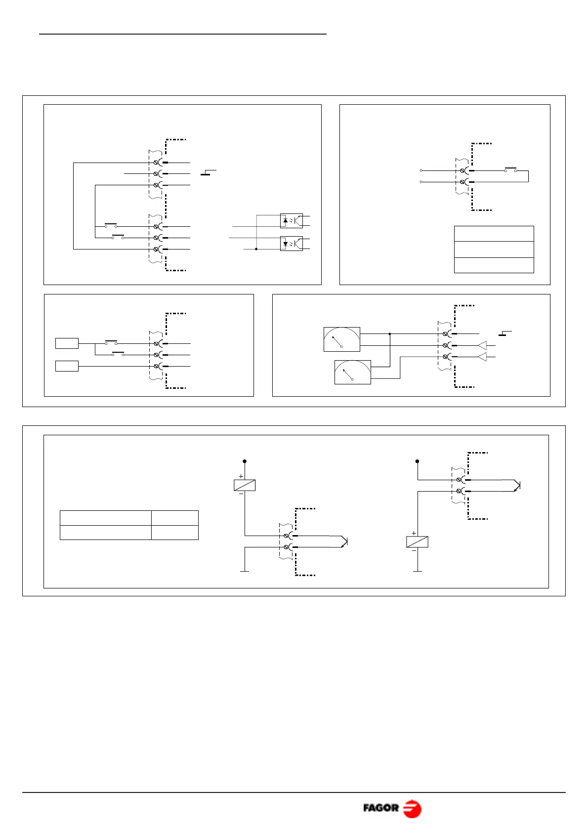
Monitoring signals:Enable signals:
Drive OK switch:
V
V
±10V
±10V
Velocity
Current
4
3
5
SPEED
DRIVE
7
6
DR.OK
To the safety
chain.
COMMON
0 V
24 V
Drive OK:
0.6A - 125Vac
0.6A - 110Vdc
2A - 30Vdc
Enable signals using ±10V voltage:
X1
SPEED
DRIVE
COMMON
2
1
3
-10 V
+10 V
X2
X2
4
5
X2
X1
3
Connection of the monitoring and control signals.
Monitoring: The drive offers +10Vdc at its "velocity" output when, receiving the maximum
command of +10V, the motor turns at the calculated speed. The "current" output offers +10Vdc
when the drive provides its peak current.
Warning Output:
2
1
X2
C
E
+ 24 Vdc
2
1
X2
C
E
+ 24 Vdc
Maximum current
Maximum voltage
100 mA
50 Volts
 Loading...