110
(MT11 - Gb2012)
JP2
329150
JP2
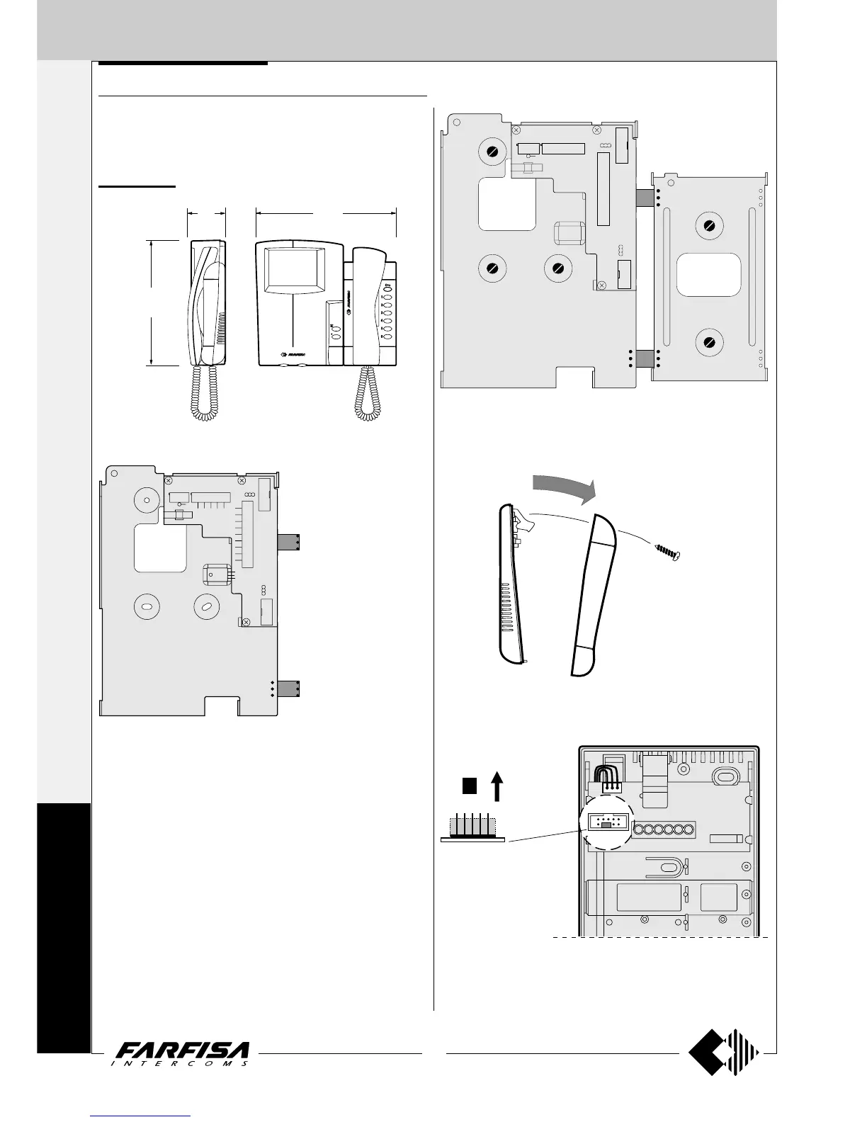
4) Remove the mobile jumper of connector JP2 of the intercom.
3) Remove the intercom cover.
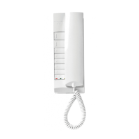
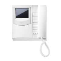
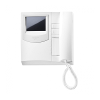
VIDEO INTERCOM
Installation steps for monitor ST7100 (or ST7100C), intercom ST720,
brackets WB7100 and WB700 and table adapters (if required) for the
realisation of an internal station with video intercom functions.
Wall version
JP1
J2
JP3
JP4
H
1
2
3
9V
9R
9M
5
F
4
Y
XPP 8
1
C
C
V
M
V
R9
JP5
J1
JP2
1
2
3
1
14
U1
1
10
3
2
1
1) Splice the bracket WB700 with the WB7100 inserting the 2 plastic
templates in the proper holes.
JP1
J2
J1
JP2
1
2
3
3
2
1
2)Fix the 2 brackets to the wall following the indications of drawing 1 on
page 108.
249
67
224
INTERNAL STATIONS
4+1
INTERCOMS *
7+1
VIDEOINTERCOMS
S
T
U
D
I
O