J
Jennifer BlanchardJul 27, 2025
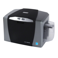
What to do if my Fargo C50 has communication errors?
- VValerie BaileyJul 27, 2025
If you are experiencing communication errors with your Fargo Printer, ensure that your system meets the minimum requirements, the printer driver is correctly installed, and adequate disk space is available. Additionally, try printing a test print to diagnose the issue.