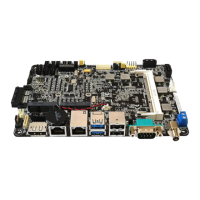
7. System panel connector (10-pin F_PANEL1)
Thisconnectorsupportsseveralchassis-mountedfunctions.
• SystempowerLED(2-pinPWR_LED)
This2-pinconnectorisforthesystempowerLED.Connectthechassis
power LED cable to this connector. The system power LED lights up when
youturnonthesystempower,andblinkswhenthesystemisinsleepmode.
•
Hard disk drive activity LED (2-pin HDD_LED)
This2-pinconnectorisfortheHDDActivityLED.ConnecttheHDDActivity
LEDcabletothisconnector.TheHDDLEDlightsuporasheswhendatais
readfromorwrittentotheHDD.
•
ATX power button/soft-off button (2-pin PWR_BTN)
This 2-pin connector is for the system power button.
•
Reset button (2-pin RESET)
This 2-pin connector is for the chassis-mounted reset button for system
reboot without turning off the system power.
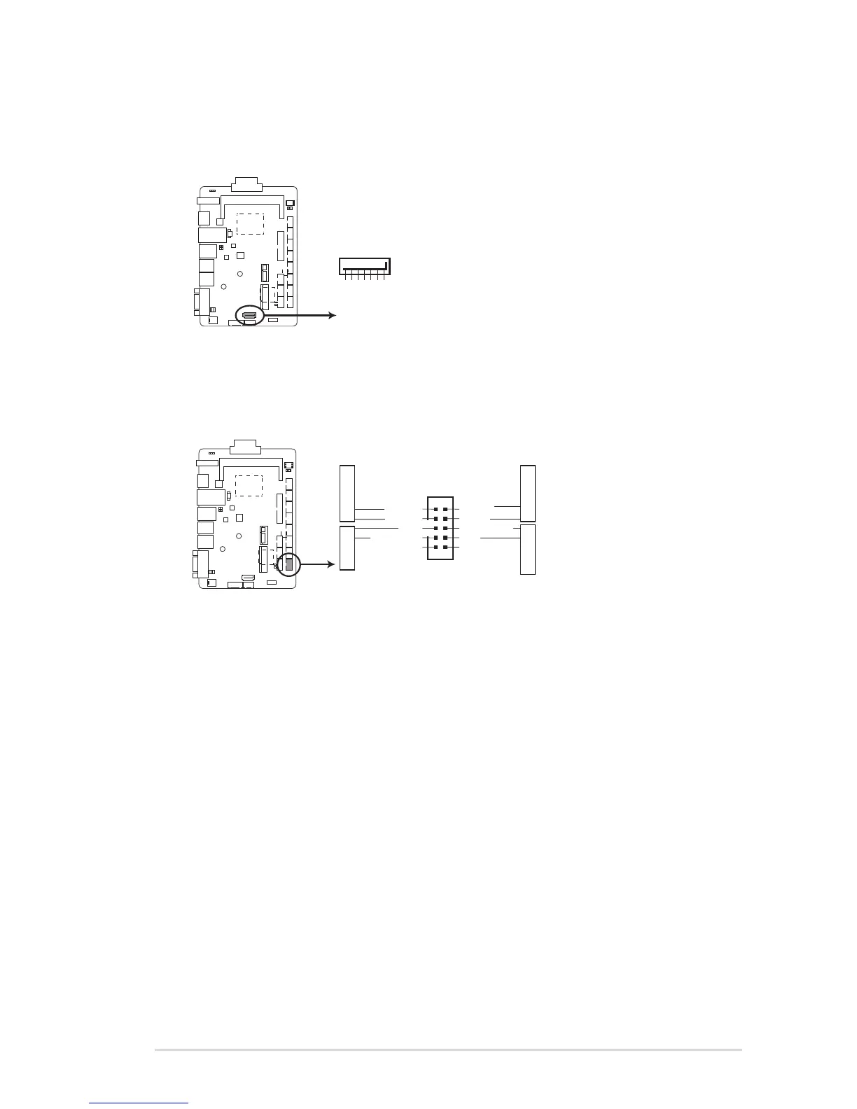
6. Serial ATA 6.0Gb/s connectors (7-pin SATA6G1)
TheseconnectorsconnecttoSerialATA6.0Gb/sharddiskdrivesand
opticaldrivesviaSerialATA6.0Gb/ssignalcables.
FAY-003