EasyManuals Logo

Feig Electronic OBID i-scan ID ISC.LRM2500-A User Manual

Feig Electronic OBID i-scan ID ISC.LRM2500-A
32 pages
To Next Page IconTo Next Page
To Previous Page IconTo Previous Page
Page #13 background imageLoading...
Page #13 background image
OBID
i-scan
®
HF
Installation
ID ISC.LRM2500-B
FEIG ELECTRONIC GmbH
Page 13 of 32
M01111-4e-ID-B.docx
470
+
IN1
-
820
J2
J1
24 V
470
+
IN2
-
820
J4
J3
24 V
470
+
IN3
-
820
J6
J5
24 V
GND
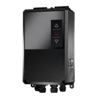
Figure 8: Possible internal power supply for the optocouplers
The input LED for the optocouplers are internally connected to a series resistor of 1290 and are
limited to an input current of max. 20mA. For voltages of less than 10V a part of the series
resistance must be jumpered (J1, J3, J5) accordingly.
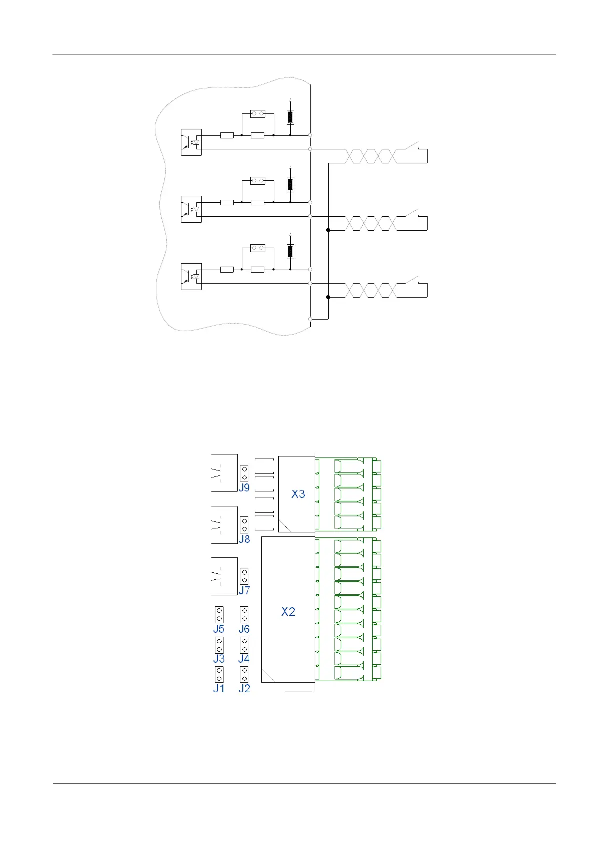
Figure 9: Position of the Jumper J1- J9

Questions and Answers:

Question and Answer IconNeed help?

Do you have a question about the Feig Electronic OBID i-scan ID ISC.LRM2500-A and is the answer not in the manual?

Feig Electronic OBID i-scan ID ISC.LRM2500-A Specifications

General IconGeneral
BrandFeig Electronic
ModelOBID i-scan ID ISC.LRM2500-A
CategoryControl Unit
LanguageEnglish

Related product manuals