EasyManuals Logo

Feig Electronic OBID i-scan ID ISC.LRM2500-A User Manual

Feig Electronic OBID i-scan ID ISC.LRM2500-A
32 pages
To Next Page IconTo Next Page
To Previous Page IconTo Previous Page
Page #14 background imageLoading...
Page #14 background image
OBID
i-scan
®
HF
Installation
ID ISC.LRM2500-B
FEIG ELECTRONIC GmbH
Page 14 of 32
M01111-4e-ID-B.docx
Note:
The input is configured for a maximum input voltage of 24 V and an input current of
maximum 20mA.
Reversing the polarity or overloading the input will destroy it.
Jumper
Description
J1
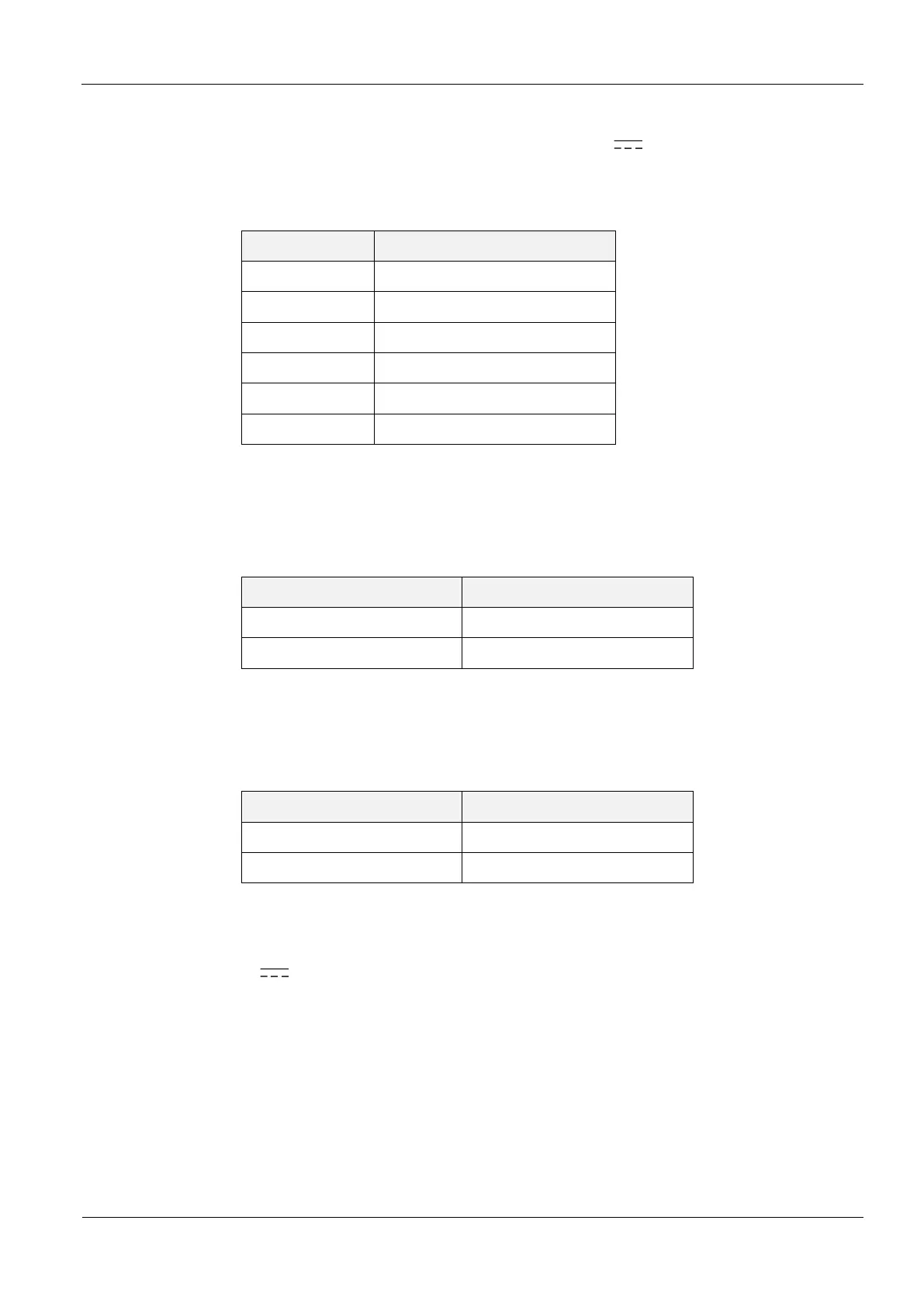
Series resistance IN1 (X2)
J2
VCC IN1 (X2)
J3
Series resistance IN2 (X2)
J4
VCC IN2 (X2)
J5
Series resistance IN3 (X2)
J6
VCC IN3 (X2)
Table 4: Jumpers for inputs IN1,IN2 and IN3
Table 5 shows the required external series resistances for the various external voltages
External voltage U
ext
Jumper J1/J3/J5
5 V ... 10 V
ON
10 V ... 24 V
OFF
Table 5: Required external series resistance
Table 6 shows the jumper setting for external or internal supply voltage
Jumper
Jumper J2/J4/J6
external voltage
OFF
internal VCC voltage
ON
Table 6: Internal / External supply voltage
Note:
The internal 24V voltage for supplying the DC voltage on the digital inputs is not
protected by the fuse F1.
Using internal and external voltage at the same time can destroy the reader.

Questions and Answers:

Question and Answer IconNeed help?

Do you have a question about the Feig Electronic OBID i-scan ID ISC.LRM2500-A and is the answer not in the manual?

Feig Electronic OBID i-scan ID ISC.LRM2500-A Specifications

General IconGeneral
BrandFeig Electronic
ModelOBID i-scan ID ISC.LRM2500-A
CategoryControl Unit
LanguageEnglish

Related product manuals