4 Operating and Display Elements
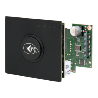
4.1 LEDs
Table 14 shows the LED configuration.
"RUN-LED 1"
- Indicates proper running of the internal Reader software (DSP)
- Comes on during Reader initialization after power-on or after a
reset.
Diagnostic 1: RF communication / EEPROM status
- Short flashing indicates errorless communication with a
transponder on the RF interface
- Flashes alternately with V1 after a reset following a software
update
- Flashes alternately with V1 in case of a data error when
reading the parameters after a reset
Diagnostic 2: Host communication
- Short flashing indicates sending of a protocol to the host on the
RS232 / RS485 / USB and LAN-Interface
Diagnostic 4: RF warning
- Comes on when there is an error in the RF section of the
Reader. The error type can be read out via software over the
RS232 / RS485 / USB and LAN-Interface
Table 14: LED configuration
 Loading...