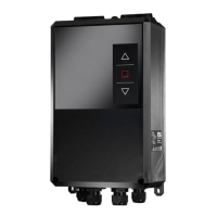
3.8 Relay (X2 / REL1, REL2, REL3)
The relay outputs are all a normally open contact. These outputs, which are located on terminals
X2, are galvanically isolated from the Reader electronics and must therefore be externally
supplied. The external voltage may however be provided by the card using jumper J7; J8; J9. All 3
outputs are identical and may be configured individually.
IN1-
REL3-COM
REL2-COM
REL1-COM
GND
IN3-
IN2-
GND
OUT2-E
IN1+
OUT1-C
GND
IN3+
IN2+
OUT2-C
REL3-NO
REL2-NO
REL1-NO
24V
OUT1-E
X2
Figure 12: Relay Outputs on terminal X2
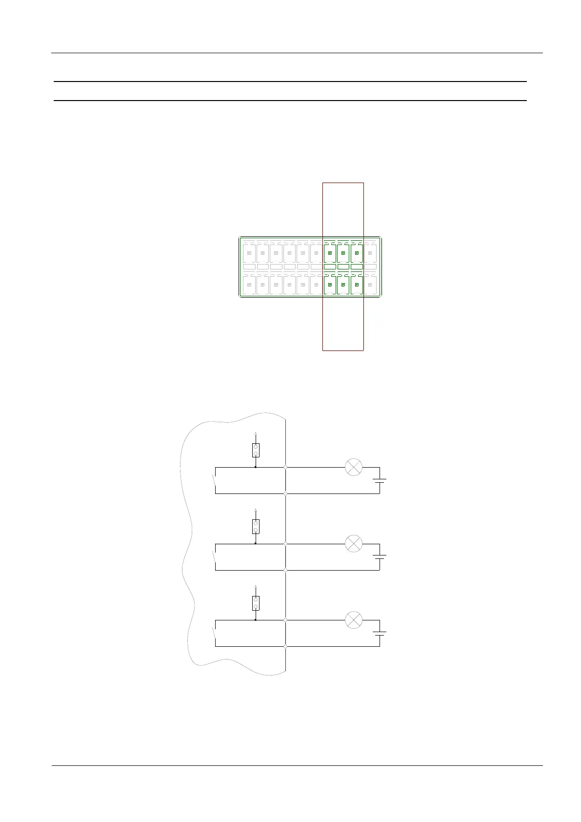
REL1
COM
N0
NO
COM
Uext
J7
24 V
REL2
COM
N0
NO
COM
Uext
J8
24 V
REL3
COM
N0
NO
COM
Uext
J9
24 V
Figure 13: Internal and possible external wiring of the relay output’s with external voltage
 Loading...