REL1
COM
N0
NO
COM
J7
24 V
REL2
COM
N0
NO
COM
J8
24 V
REL3
COM
N0
NO
COM
J9
24 V
GND
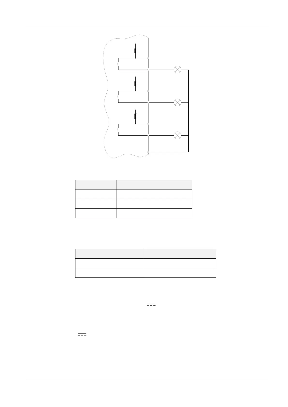
Figure 14: Internal and possible external wiring of the relay output’s with internal voltage
Table 7: Assignment of the jumpers to the relay output
Table 8 shows the jumper setting for the external voltage or internal VCC voltage
Table 8: Internal- / External voltage supply
Notes:
The relay output is configured for max. 24 V / 1 A.
The relay output is intended for switching resistive loads only. If an inductive load is
connected, the relay contacts must be protected by means of an external protection
circuit.
The internal 24V voltage for supplying the DC voltage on the relays is not protected
by the fuse F1.
Using internal and external voltage at the same time can destroy the reader.
 Loading...