VEK MNH1-R24-A QUICK START GUIDE 1.4 EN
3.3.2 Relay outputs with changeover contact
The relay outputs are designed as changeover contacts. This allows the
contacts to be connected as normally closed (NC) or as normally open
(NO) contacts. The relays are potential-free and suitable for many
different switching modes.
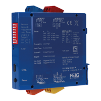
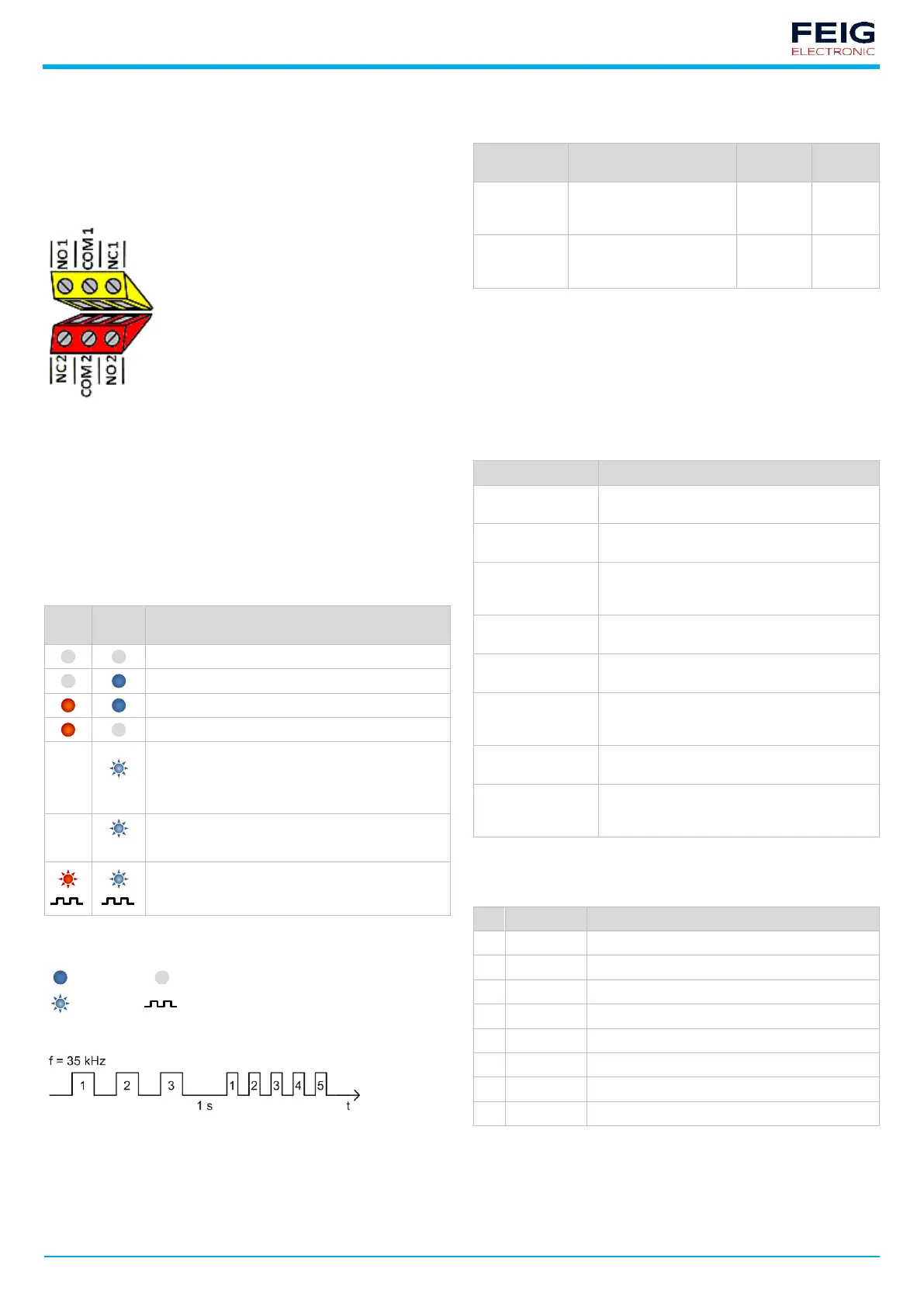
The analogue outputs of the (R24) relay variants are connected to the red
and yellow terminal blocks as shown in the following illustration.
Normally open contact to output 1 or
output 2
Common contact to output 1 or
output 2
Normally closed contact to output 1
or output 2
Fig. 4: Relay connections 1 (yellow) and 2 (red)
4 Description of functions
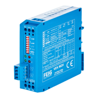
4.1 LED status indicators
The LEDs (light emitting diodes) on the front side indicate the state of the
loops and the detector.
There are two LEDs for each loop channel:
• The red LED indicates the coverage status of the respective loop
• The blue LED indicates the operating status of the detector
No power supply, detector inactive
Detector ready, loop connected, no object detected
Detector ready, loop connected, object detected
No loop connected, loop break, loop closure
Ready for operation following earlier, now rectified,
loop error or
settings changed with Detector Tool (DIP switch not
up-to-date)
Frequency alignment is running
After frequency adjustment, both LEDs
simultaneously display the set loop frequency in a
flash code (see Flash code illustrated example)
Tab. 5: LED signal colours
Key to LED symbols
LED flash code following a frequency alignment
Fig. 5: LED display of loop frequency
4.2 Reset button
The device is reset using the reset button on the front as follows:
runs a frequency
readjustment and clears the
LED fault messages
resets the device to factory
settings (DIP switch default
settings)
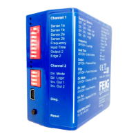
4.3 DIP switch settings
Depending on the output function settings, presence, pulse and loop fault
signals are output.
For the pulse signal, it is also possible to select whether an output should
occur when a loop is driven past or vacated.
In addition to inversion of the output signal, both outputs can individually
be permanently switched on or off.
Switch-on threshold for the signal output when a
loop is covered
Frequency of the loop oscillating circuit in two
levels
Hold time until
readjustment
Maximum duration of the output signal up to the
automatic frequency readjustment of the loop
channel
Switching between continuous and pulse signal
on output 2
Time of output signal for activated pulse signal
on output 2
Switching between open circuit (not inverted)
and closed circuit principle (inverted) for the
output signals
Switching between presence and travel direction
detection for both outputs (dual-channel variants)
Evaluation logic of the travel direction when
loops are covered, depending on the application
(see full operating manual!)
Tab. 7: Description of the settings
The single-channel variants have an 8-pole DIP switch for configuring the
detector.
Hold time until readjustment
Output signal 1 inversion
Output signal 2 inversion
Tab. 8: DIP switch assignment (default)
 Loading...