18
La Lw Ln Lw La
Wa
Wn
Ww
Wmax
Wa
Lmax
!
Bandsaw
FB 540/640/740/840/940
The machine can either be lifted and transported with a
fork carriage or with a crane sling with a hoisting power
of at least 2000 kg.
The following points are important for a correct and ef-
ficient machine installation:
• Install the machine in such a way as not to amplify
the vibrations and machine noise.
• Ensure that workplace lighting is adequate.
• If the machine is to be installed between other ma-
chines, leave at least 80 cm distance in-between, in
order to avoid collisions when cutting large work-
pieces and to allow the use of equipment such as roll
supports and additional tables.
• There are 4 threaded holes located in the base plate
of the machine where the levelling screws supplied
with the machine can be screwed into.
6.2.1 Safety instructions
Fig. 5: Pallet jack
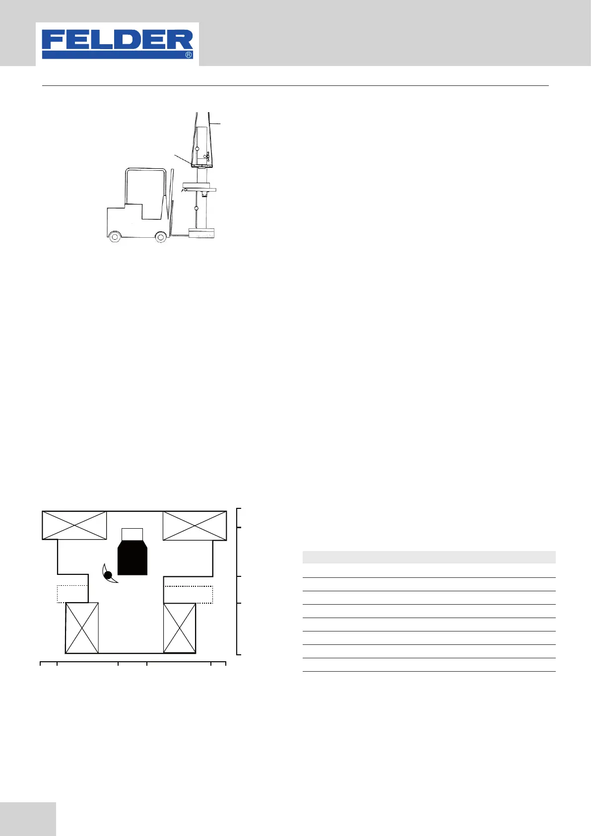
Fig. 6: Diagram
Setup and installation
Scale 1:100
Lmax : Max. length
Wmax : Max. width
Ln: Machine length
Wn : Machine width
Lw : Working length
Ww : Working width
La: Auxiliary support area length
Wa : Auxiliary support area width
• In the base plate are also 4 additional bores, which
are to screw the machine to the floor. However, do
not overtighten the mounting screws, as this will as a
result, increase vibrations. It is also recommended to
lay vibration dampening materials between the floor
and the machine.
Look at the diagram in Fig.6 before setting up the ma-
chine.
!Wood 80x40x360