Page 27
BB
BB
B
US2US2
US2US2
US2
BB
BB
B
US2US2
US2US2
US2
Code 97462I-1 V07_09
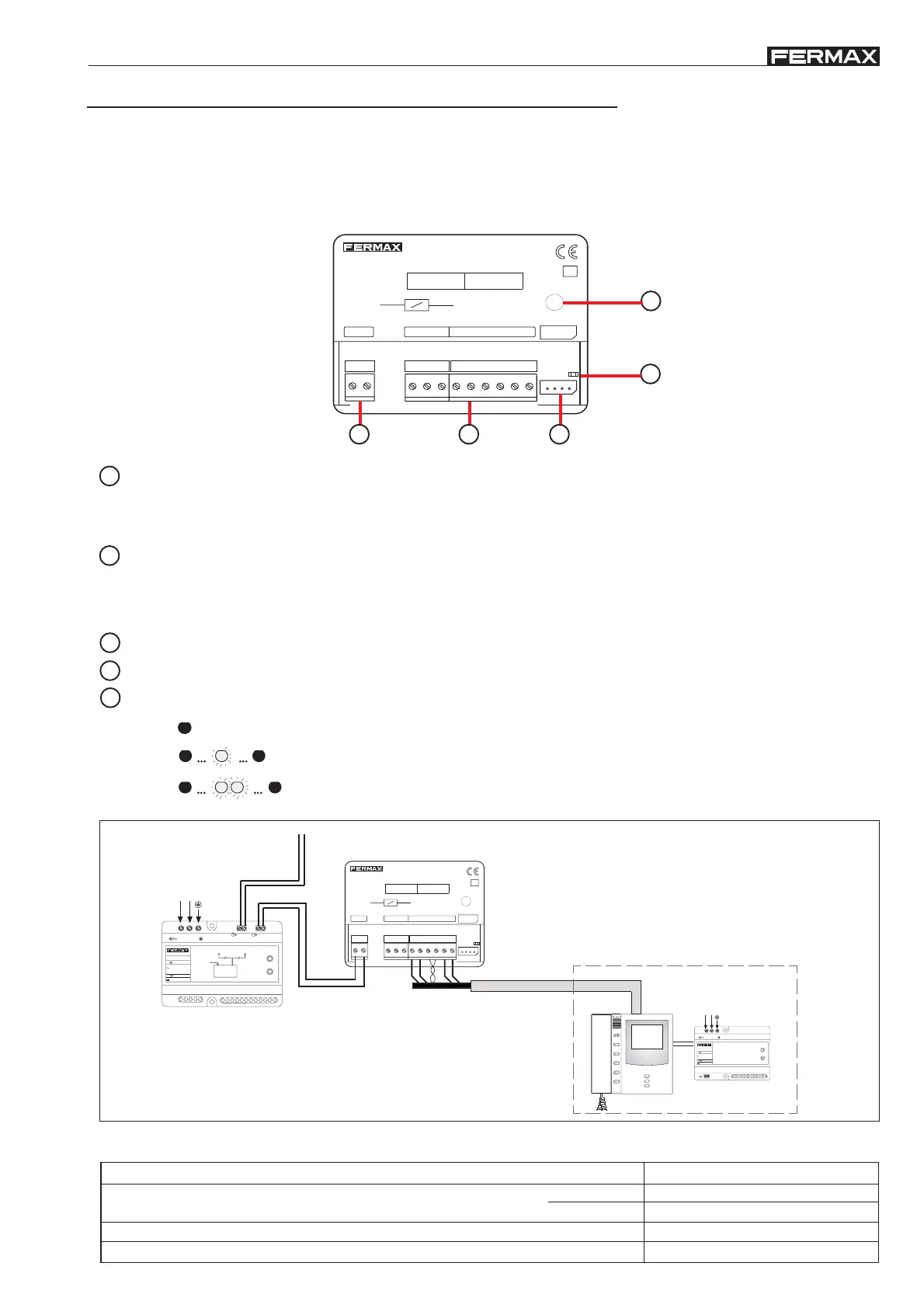
MDS/BUS2 DECODER
* Technical characteristics
Consumption
Operating Temperature
12 Vdc
on standby
active audio
0 , +60 °C
20 mA
30 mA
Power supply
The ‘MDS/BUS2 decoder’ acts as an interface between the BUS2 system and the MDS system, enabling the connection
between the MDS reception and MDS panels in BUS2 systems, whilst extending the range of services offered by the
BUS2 system: locked entrances with multiple general MDS access points, central receptions, etc.
For more information on the combination of MDS and BUS2 systems, please consult the ‘MDS/BUS2 Technical Manual’.
PC: Connect for programming via PC (using PC-Decoder interface ref.24661 and Decowin software).
MDS: Bus installation MDS connection (Direct reception).
+,-: 12 Vdc power supply.
D1,D2: MDS bus data. RS-485.
2,6: Audio panels/MDS reception (2: entry panel direction, 3: residence direction).
2
3
PGM: Programming button. Puts decoder in programming mode.
1
CN1: BUS2 system bus connection:
B,B: Data, BUS2 audio and video.
Ct: Video activation distributor. 0v on standby; 10 Vdc with the decoder active. Max. 100 mA.
5
DL1: Status led:
4
Decoder is not programmed.
Programmed and reception in night mode (reception does not receive calls).
Programmed and reception in day mode (reception receives calls).
3s3s
off
on on
off
3s3s
off
on
off
off
D2
26
D1
-
+
PC
CT
V-
MDSBUS-2
VERSION
D2 2 6D1-+
BB
PC
PGM
DECODER MDS-BUS2
CT V -
DIRECCIONES
ADDRESSES
INI. FIN.
B
B
DL1
5
4
321
D2
26
D1
-
+
PC
CT
V-
MDSBUS-2
VERSION
D2 2 6D1-+
BB
PC
PGM
DECODER MDS-BUS2
CT V -
DIRECCIONES
ADDRESSES
INI. FIN.
B
B
DL1
24 V ; 2 A
50-60 Hz
100-240 V ; 1,2A
INPUT
OUTPUT
V100-240
BUS BUS
PRW BUS
PRW BUS
22
Vac
OVERLOAD
ON
100-240V
2-wire bus.
(B,B)
BUS2 power supply
MDS/BUS2 decoder
Bus MDS
(4 wires + twisted pair)
12 Vdc
50-60 Hz
100-240 V ; 1,2A
INPUT
OUTPUT
V100-240
OVERLOAD
ON
Vac
12 Vdc
MDS installation
Reception
12Vdc power supply
2-wire bus.
(B,B)
Dimensions (Height x Width x Depth) 61 x 86 x 21 mm // 2.4 x 3.4 x 0.8”