Page 34
Code 97462I-1 V07_09
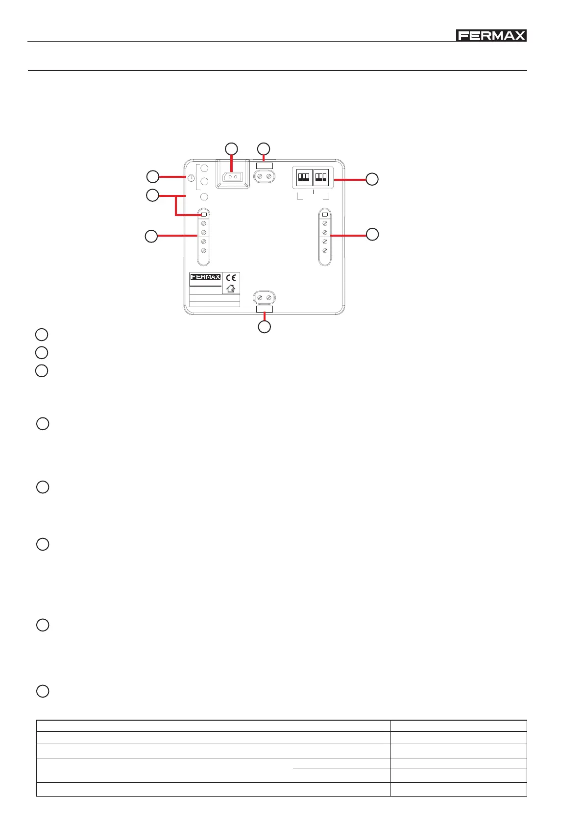
BB
BB
B
US2US2
US2US2
US2
BB
BB
B
US2US2
US2US2
US2
BUS2 relay (Ref.3247)
The BUS2 Relay makes potential free relays available in BUS2 systems, with various functional and activation
modes to be configured:
- relay activation using commands generated from the residential terminals and/or entry panels.
- external activation: using buttons, additional external switches, etc.
The BUS2 relay is installed in an intermediate point on the bus without the need for the additional wiring.
BUS INPUT: BUS2 Input Connector.
1
3
BUS OUTPUT: BUS2 Output Connector.2
Potential-freerelay contacts (max 5A):
· C, NO, NC: Common, normally open, normally closed.
+12: Auxiliary voltage output 12Vdc, 0.5A max. current.
Led Relay ON: Active relay output indicator LED
4
External relay control:
· ACT/EXT, GND: Relay activation through external contact. Activates the relay as a result of a short circuit
between ACT/EXT and GND terminals.
ENAB/DISABLE, GND: Disables any action taken on the relay (as a result of an external command or
activation) during a short circuit between both terminals.
5
CONFIG: Configuration dipswitches
· DSW1 MODE: Relay operational mode configuration.
· DSW2 COMMAND: Configuration of control mode (control commands, external activation)
See section “BUS2 relay configuration”
6
PRG: Programming button.
Led Relay ON: Relay indicator LED in programming mode.
BUS2 addresses can be programmed on the BUS2 relay (from 1 to 199) so that they will only respond to activation
commands from a device whose address corresponds to one of those programmed at an earlier position on the
relay.
See section “BUS2 relay configuration”
7
Activation TIME Allows the relay’s activation time be programmed (from 1 to 600 seconds) when it is configured
in the Timed operating mode. (Default value: 5 seconds).
· SEC: Each press increases the activation time by 1 second.
· 10xSEC: Each press increases the activation time by 10 seconds.
See section “BUS2 relay configuration”
* Technical characteristics
8
TEST: Connector available for connecting the “BUS2 verifier” (see section “BUS2 verifier”).
BB
BB
BUS-2 OUTPUT
BUS-2 INPUT
led PRG
ACTV EXT
GND
INHAB/DISABLE
OUTPUT 12V 0.5A
MODULO RELE
BUS 2
REF. 3247
MADE IN SPAIN
GND
relay ON
+12V
NC
NO
C
RELAY MODUL
BUS 2
PRG
10xsec
sec
1 2
ON
3 1 2
ON
3
DSW1
TEST
CONFIG
DSW2
2
6
5
1
4
3
7
8
Consumption
Operating Temperature
24 Vdc
activated
33 mA
Power supply
Dimensions (Height x Width x Depth) 86 x 89 x 26 mm // 3.4 x 3.5 x 1”
-0 , +50 °C // 32, +122ºF
Relay contacts
Maximum voltage
Maximum current
30Vdc - 220 Vac
5 A