-5-
[11]
[10]
[12]
[13]
[9]
[1]
[3]
[4]
[8]
[7]
[6]
[5]
[2]
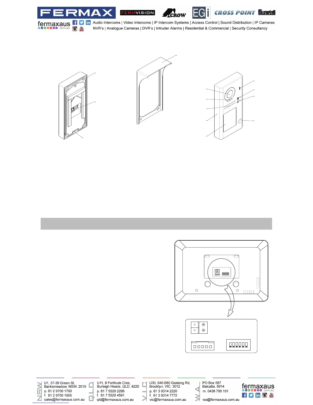
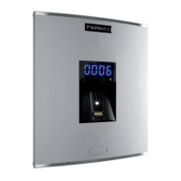
[1] Microphone
[2] UNLOCK indicator
[3] CALL indicator
[4] Call button
[5] Nameplate
[6] Front panel
[7] Speaker
[8] Night view LED
[9] Camera lens
[10] Rainy cover
[11] Mounting hook
[12] Connection port
[13] Screw hole
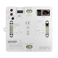
Terminal Description
1 2 3 4 5 6
ON DIP
L2
L1
DIP Switches
SW+
SW-
RING
GND
NC
L1
L2
1 2 3
ON DIP
4 5 6
L1,L2: Bus line terminal.
SW+,SW-: Extra door bell call but-
ton connection port.
Ring,GND: Extra buzzer connection
port.
NC: Undened.
DIP switches: Total 6 bits can be
congured.
• Bit1~Bit5: User Code setting.
• Bit6: Set to ON if the monitor is at
the end of the line or works with
DBC4A. Otherwise, set to OFF.